DEIMOS instrument control GUI

Introduction

The new DEIMOS control GUI is a replacement for the old Dashboard GUI. The control GUI is the main interface to operate DEIMOS. The control GUI can be started from the VNC background menu by selecting DEIMOS Control Menu → Subcomponents... → Start DEIMOS control GUI.

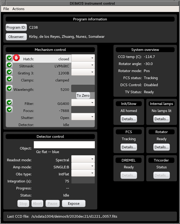
The following figure shows the layout of the main page of the control GUI:

Main page of the DEIMOS control GUI

The control GUI is composed of the following areas:

From the operation point of view, the control GUI has the following components:

  • Section header titles: This is the header title for each of the GUI sections or areas. Some of these titles operate as toggle buttons to enable/disable the corresponding area. For instance, in the
  • rotator GUI, the Sky mode and Manual mode to enable/disable the corresponding area. When an area is disabled, all its components are grayed out and it becomes non interactive. Simply, left-click on the header to make the area interactive. Not all header/titles act as enable/disable toggle buttons.
  • Details buttons: A new GUI will popup when left-clicking on the details buttons
  • Pulldown menus: These are used to select different elements of a component. For instance, a pull down menu is used on the detector control area to select the CCD amplifier area.
  • Text boxes: These can be used to input values such as the central wavelength on the mechanism control area or the exposure time on the Detector control area.
  • Apply buttons: These buttons show up when the desired value of a given component differs from the current value. Once you are happy with the desired value, the Apply button needs to be hit to actually move the stage or change a value.
  • Apply all/Reset all: The Apply all button allows you to change multiple values of the same area simultaneously. The Reset all button can be used if a selelection for one of the components was made by mistake and you dot not want the desired change to take effect.
  • Status flags: These indicate the overall state of a stage or component:
    • White check mark on a green background: The component is is ready to be used.
    • White cross with red background: The component is faulted and needs attention.
    • White horizontal bar with red background: The component is not calibrated. It needs to be recalibrated.
    • Gray gear wheels: The component is moving or transitioning from one state/position to another.
    Status flats are interactive. If you left-click on a status flag, a new GUI with detailed information about its corresponding component will popup.
  • Stop signs: These are the signs showing a white hand over a red background. They are exclusive of the mechanism control area to indicate where the light beam is stopped in the optical path.

Components

File pulldown menu

This puldown menu has only one entry, Quit, which is used to exit the DEIMOS control GUI.

Actions pulldown menu

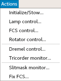
The following figure shows the components of the Actions menu:

Actions menu of the DEIMOS control GUI
Some of the components of the actions menu are an alternative way to open the following: Addtionally, the actions menu can also be used to open the following:

Program ID and observers definition

This area of the GUI is used to define the program ID and the list of observers. It is important to set the program ID correctly, because this information is used by Keck Observatory Archive (KOA) to determine who is the owner of the images. The program ID can be founf on the telescope schedule.

On DEIMOS split nights, the Program ID and Observer fields need to be changed every time data are taken for one or the other program. Additionaly, the output data directory must be changed when switching programs using the following command on a polo terminal:

outdir [data_directory]
For instance, when toggling between to DEIMOS programs on Dec 22, 2020, one would use:
outdir /sdata1005/deimos9/2020dec22
outdir /sdata1005/deimos9/2020dec22_B
The outdir script keeps track of the frame numbers on each data directory to make sure that images are not overwritten. The outdir script without arguments displays the current data directory on the terminal.

Mechanism control area

This area of the GUI is used to change the optical configuration of the instrument. There are 5 columns on this area, from left to right:

  • Stage status flag.
  • Light beam blocking status.
  • Stage name.
  • Name of the component inserted in the optical path
  • Stage value selector

Before taking any science data, make sure that all the status flags on the left hand side of the area are white check marks with a green background.

Before taking on-sky data, make sure that the hatch is open.

Multiple mechanisms can be moved simultaneously with the Apply all button, but there is a catch: If you are switching between two different gratings, the first time that you define a grating/wavelength combination, make sure to move the grating first and then set the central wavelength. Once you have done this for both combinations of grating/wavelength, the GUI will remember which wavelength goes with which grating, so you can simply change the grating, and the desired wavelength for that grating will be selected automatically.

The status flags will look like gear wheels while the stage is moving. A progress bar for each stage that is moving will appear on the right hand side of the mechanism control area. Onces all the moves are completed, all status flags should turn to white check marks on a green background and the pregess bars should disappear.

Detector control area

This area of the GUI is used to control the detector parameters and the exposures with the science detector.

For MOS and long-slit science programs, in practice, the Readout mode field should be set to Spectral and the Amp mode should be set to SINGLE:B at the beginning of the afternoon checkout and not change it for the rest of the night. There are various scripts and observing sequences that will change this setup temporarily, e.g. the internal focus sequence, the MIRA script to focus the telescope or the fine alignment images for MOS observations, but the scripts will return the detector to the original configuration once they are done.

For imaging programs, the the Readout mode field should be set to Direct and the Amp mode should be set to SINGLE:B.

Please, check the science detector status page to see if there are detector setup recommendations that differ from the values indicated in the previous paragraph.

Last image filename

Display the full path to the last image saved on disk.

System overview area

This area of the GUI shows general information about the current status of the sytem. The displayed fields are:

  • CCD temp (C): Detector temperature. The DEIMOS CCD mosaic operation temperature is -115C, plus or minus a few tenths of a degree Celsius.
  • Roator angle: Rotator physical angle. This is not the sky position angle.
  • Rotator mode: When observing at night, the rotator mode should be Track. To be able to rotate the instrument during the day, the rotator mode should be Pos. To change the rotator mode see the DEIMOS rotator GUI.
  • FCS status: Overall FCS status. When exposing spectral science data on sky, the status should be Tracking
  • DCS control: This should be Enabled when observing at night. In this case, the rotator is controlled by the telescope control system, also know as the Drive Control System (DCS).
  • TV Status: This is the status of the guider camera. It should be Ready when observing.

Last modified: 03/07/2021 09:37
Send questions or comments to:DEIMOS Support

The information on this page is the property of the W. M. Keck Observatory. The contents of this page or any part thereof shall not be copied or otherwise reproduced or transferred to other documents or used or disclosed to others for any purpose other than observing support at the W. M. Keck Observatory and the subsequent analysis and publication of scientific data obtained from observations conducted at the W. M. Keck Observatory. All rights reserved. © W. M. Keck Observatory.