Introduction
This page describes issues that are currently affecting the DEIMOS
science detector. The page will be updated regularly with the latest
status.
Each CCD on the detector mosaic can be read using two amplifiers. In
spectroscopy mode, we use the B amplifiers (AMPMODE =
SINGLE:B), because A amplifiers are overall noisier. In
direct imaging mode, we normally use both amplifiers (AMPMODE
= DUAL:A+B) to read the detector, because the readout time is
twice as fast than with one amplifier for mask alignments. It is not
possible to read the detector using both amplifiers in spectroscopy
mode.)
February 29, 2024, the DEIMOS detector mosaic presents the
NO ISSUES when read out with B amplifiers. The
following issues with A amplifiers are still present, but the do not
affect science operations (see CCD status
for details):
- CCD5B is not sensitive to illumination. This affects the
spectra of slits placed on CCD1.
- CCD5A is not sensitive to illumination.
- CCD3A bias frames have a horizontal noise pattern. This does
not affect spectroscopic observations. It does not affect mask
alignment images either. It only affects science observations
taken in direct imaging mode. This issue can be mitigated by
taking direct imaging science data with the B amplifiers instead
of both amplifiers.
- CCD6A bias has all pixels at 1024 counts.
- CCD8A has a lower gain than the rest of the CCD mosaic. This
issue does not affect either spectroscopy or direct imaging
observations, but it prevents us from using A amplifiers as an
alternative when there are issues with B amplifiers. Additionally,
CCD8A bias frames have a horizontal noise pattern.
February 26, 2023, the DEIMOS detector mosaic presents the
NO ISSUES when read out with B amplifiers. The
following issues with A amplifiers are still present, but the do not
affect science operations (see CCD status
for details):
- CCD5A is not sensitive to illumination. Therefore, DEIMOS
spectra should always be taken with the B amplifiers
- CCD3A bias frames have a horizontal noise pattern. This does
not affect spectroscopic observations. It does not affect mask
alignment images either. It only affects science observations
taken in direct imaging mode. This issue can be mitigated by
taking direct imaging science data with the B amplifiers instead
of both amplifiers.
- CCD6A bias has all pixels at 1024 counts.
- CCD8A has a lower gain than the rest of the CCD mosaic. This
issue does not affect either spectroscopy or direct imaging
observations, but it prevents us from using A amplifiers as an
alternative when there are issues with B amplifiers. Additionally,
CCD8A bias frames have a horizontal noise pattern.
January 6, 2023, the DEIMOS detector mosaic presents the
following issues (see CCD issues for
details):
- CCD5 spectra taken with the B amplifier (CCD5B) has a bias
noise about 3 times higher than nominal and a gradient along the
detector rows. Its response to illumination is nominal. Therefore
the spectra of targets placed on CCD1 will have a readnoise
component higher than the spectra of targets placed on other
CCDs.
- CCD5A is not sensitive to illumination. Therefore, DEIMOS
spectra should always be taken with the B amplifiers
- CCD3A bias frames have a horizontal noise pattern. This does
not affect spectroscopic observations. It does not affect mask
alignment images either. It only affects science observations
taken in direct imaging mode. This issue can be mitigated by
taking direct imaging science data with the B amplifiers instead
of both amplifiers.
- CCD6A bias has all pixels at 1024 counts.
- CCD8A has a lower gain than the rest of the CCD mosaic. This
issue does not affect either spectroscopy or direct imaging
observations, but it prevents us from using A amplifiers as an
alternative when there are issues with B amplifiers. Additionally,
CCD8A bias frames have a horizontal noise pattern.
April 23, 2022, the DEIMOS detector mosaic presents the
NO ISSUES when read out with B amplifiers. The
following issues with A amplifiers are still present, but the do not
affect science operations (see CCD status
for details):
- CCD5A is not sensitive to illumination. Therefore, DEIMOS
spectra should always be taken with the B amplifiers
- CCD3A bias frames have a horizontal noise pattern. This does
not affect spectroscopic observations. It does not affect mask
alignment images either. It only affects science observations
taken in direct imaging mode. This issue can be mitigated by
taking direct imaging science data with the B amplifiers instead
of both amplifiers.
- CCD6A bias has all pixels at 1024 counts.
- CCD8A has a lower gain than the rest of the CCD mosaic. This
issue does not affect either spectroscopy or direct imaging
observations, but it prevents us from using A amplifiers as an
alternative when there are issues with B amplifiers. Additionally,
CCD8A bias frames have a horizontal noise pattern.
September 15, 2020, the DEIMOS detector mosaic presents the
following issues (see CCD issues for details):
- CCD5 spectra taken with the B amplifier (CCD5B) has a bias
noise about 4 times higher than nominal. Its response to
illumination is nominal. Therefore the spectra of targets placed
on CCD1 will have a readnoise component higher than the spectra of
targets placed on other CCDs. The same issue affects to CCD5 when
read with the A amplifier.
- CCD5A is not sensitive to illumination. Therefore, DEIMOS
spectra should always be taken with the B amplifiers
- CCD3A bias frames have a horizontal noise pattern. This does
not affect spectroscopic observations. It does not affect mask
alignment images either. It only affects science observations
taken in direct imaging mode. This issue can be mitigated by
taking direct imaging science data with the B amplifiers instead
of both amplifiers.
- CCD6A bias has all pixels at 1024 counts.
- CCD8A has a lower gain than the rest of the CCD mosaic. This
issue does not affect either spectroscopy or direct imaging
observations, but it prevents us from using A amplifiers as an
alternative when there are issues with B amplifiers. Additionally,
CCD8A bias frames have a horizontal noise pattern.
February 14, 2020, the DEIMOS detector mosaic presents the
following issues (see CCD issues for details):
- CCD5 spectra taken with the B amplifier (CCD5B) look like a
bias when illuminated with photons. This isssue has been occuring
intermittently for over a year. It affects the spectra of slits
placed on CCD1. The same issue affects to CCD5 when read with the
A amplifier.
- CCD3A bias frames have a horizontal noise pattern. This does
not affect spectroscopic observations. It does not affect mask
alignment images either. It only affects science observations
taken in direct imaging mode. This issue can be mitigated by
taking direct imaging science data with the B amplifiers instead
of both amplifiers.
- CCD8A has a lower gain than the rest of the CCD mosaic. This
issue does not affect either spectroscopy or direct imaging
observations, but it prevents us from using A amplifiers as an
alternative when there are issues with B amplifiers.
From
dsimulator to detector plane
This section describes the relative orientation between the dsimulator
user interface, mask design blueprints and detector plane. This is
intended to serve as a reference to determine which areas on the
dsimulator interface should be avoided to prevent the spectra of the
highest priority targets from being affected by any given issue on
the detector mosaic. Plesae, click on the images below for an
expanded view.
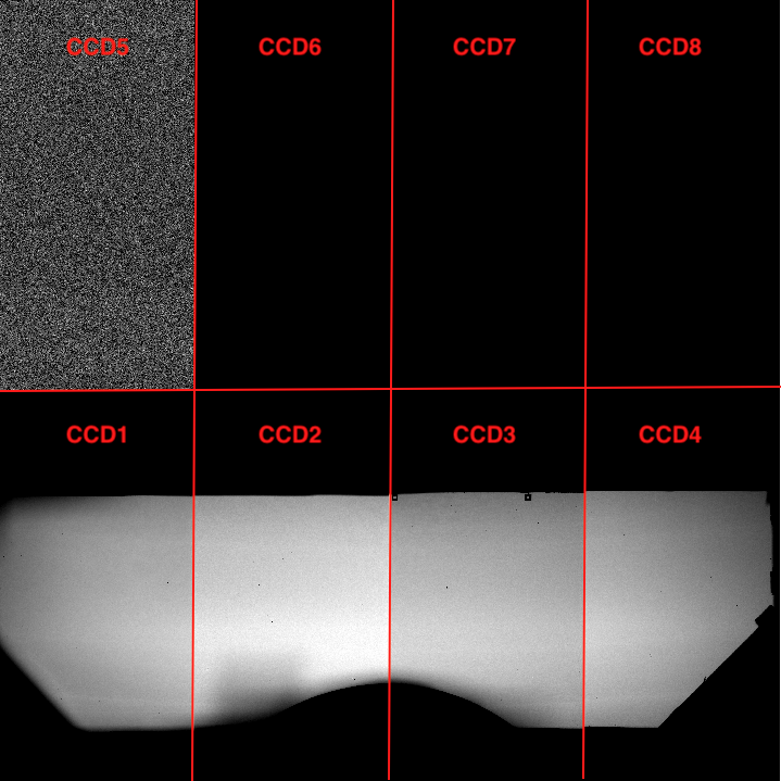
1. Mask location on the detector plane
The next figure shows the location and orientation of the instrument
focal plane with respect to the detector as it is normally seen on a
modern DS9 display tool. The image was opened using DS9 with the
option to match the coordinate system to the WCS. This is not a sky
WCS but a detector WCS that contains the relative location between
amplifiers on a DEIMOS mosaic image. This is also how the image
looks like when opened with the DEIMOS real-time DS9 GUI. The image
was taken with one of the internal calibration lamps and no mask
inserted in the optical path. Note that CCD5 looks like a bias due
to the issue described reported on February 14,
2020.
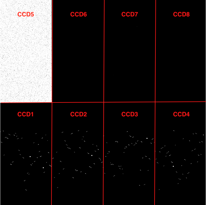
The next image was also illuminated with one of the internal
calibration lamps, but a mask was inserted in the optical path
(please, expand the image for a better visualization of the slits
and alignment boxes).
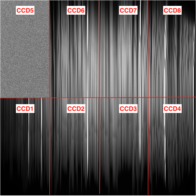
Next figure shows an internal spectral flat taken with the same
slitmask that was used to take the mask image shown in the previous
figure.
2. Blueprint and dsimulator user interface
The following figure shows the blueprint corresponding to the mask
shown in the previous section. Note that the blueprint is rotated
by 180 degrees with respect to the mask image displayed with
DS9. CCD1 is on the right-hand side in the blueprint, instead of
the left-hand side.

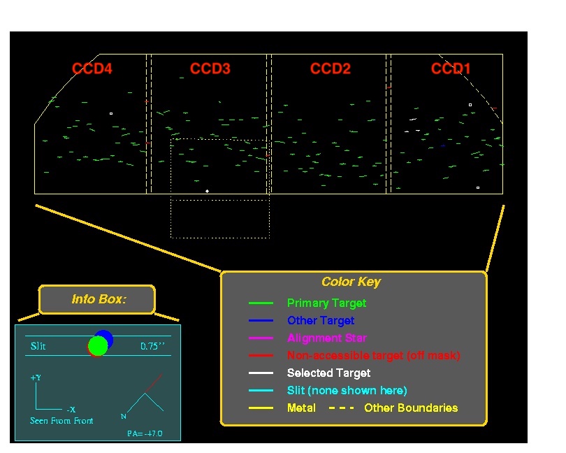
The following image shows the dsimulator user interface for a
different mask than the one shown in the image above. It is
important to note that the disimulator orientation matches the
blueprint orientation. The slitmask diagram shown in the
dsimulatior is rotated by 180 deg with respect to the image
displayed with DS9.
CCD issues
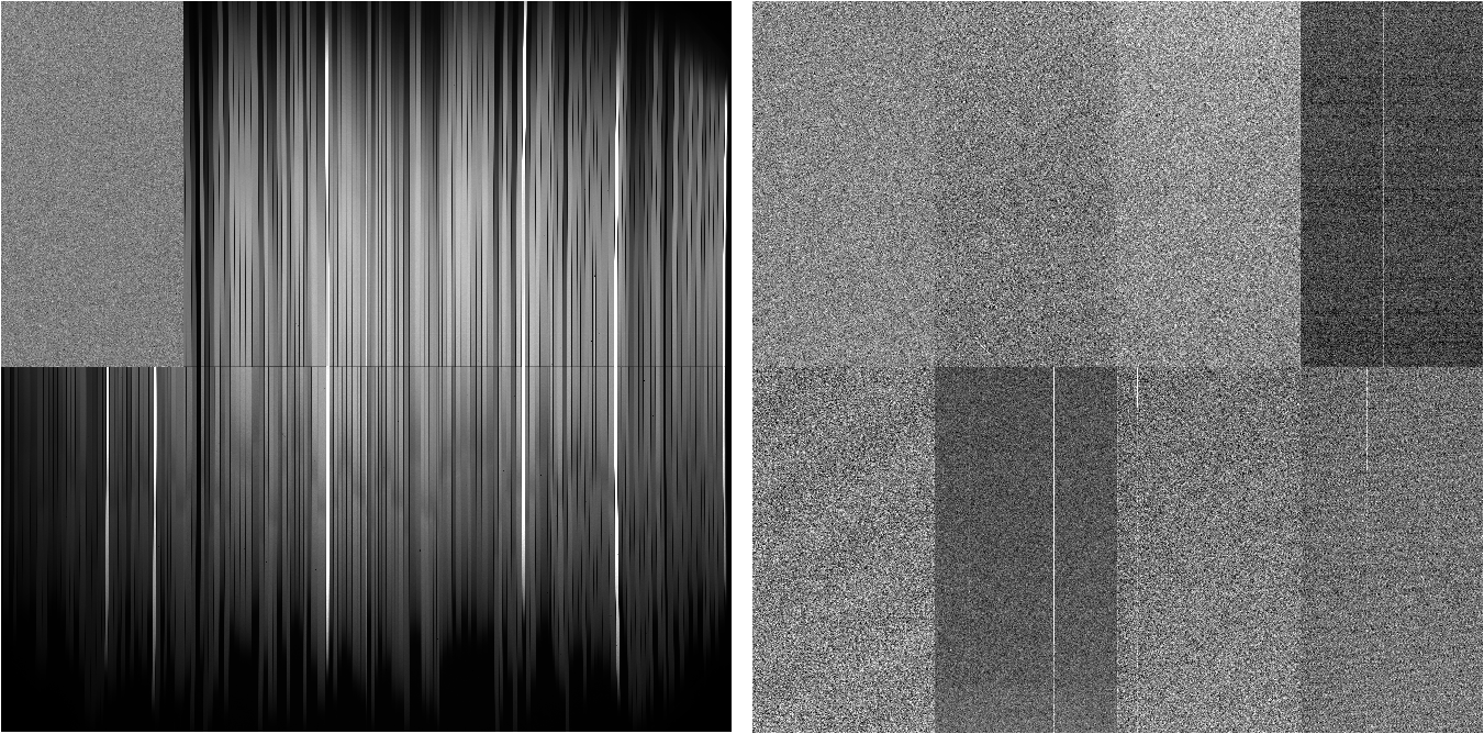
2024-02-29: CCD5 is
not sensitive to illumination
The following figure shows a flat and a bias frame taken with the B
amplifiers on June, 1 2024. The bias noise on CCD5 is nominal but
it is not sensitive to illumination.
 As a consequence, placing high priority targets on CCD1 is not
recommended if the spectral features of interest are located on the
red side of the spectrum. Please,
see section on the relative orientation
between the dsimulator diagram and the detector plane to
visualize the location of CCD1 on dsimulator. Alignment boxes placed
on CCD1 will not be affected by the CCD5 issue.
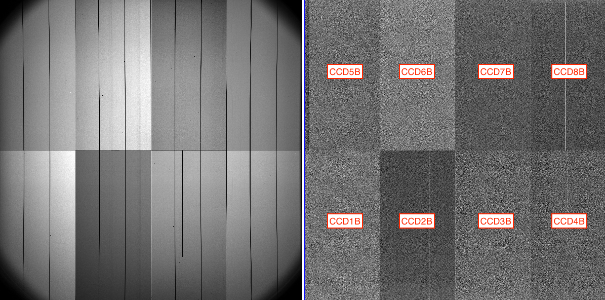
2023-02-26: All CCDs
(B amplifiers) show nominal bias noise and response to
illumination
The following figure shows a flat and a bias frame taken with the B
amplifiers on March 14, 2023. The bias noise and response of
illumination of all CCDs is nominal.
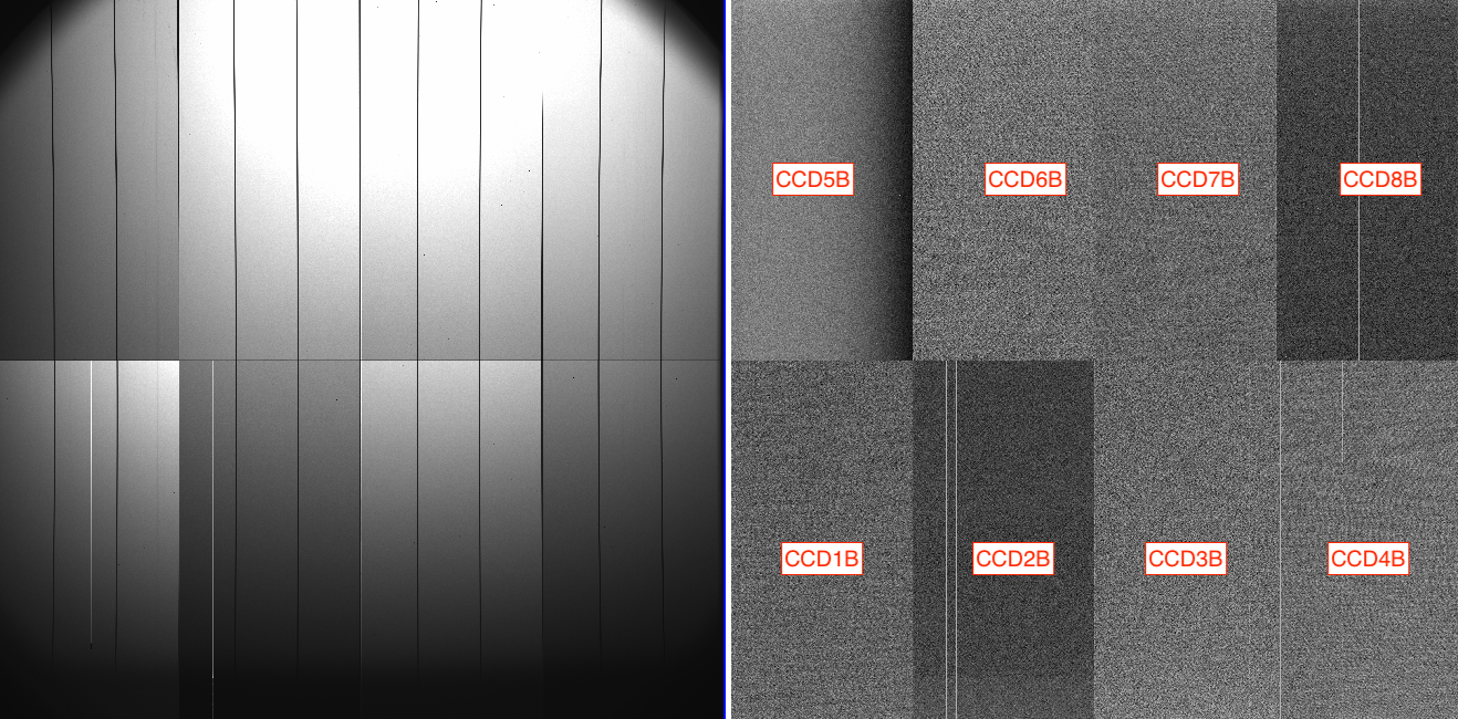
2023-01-06: CCD5B high
bias noise with gradient but nominal throughtput
The following figure shows a flat and a bias frame taken with the B
amplifiers on January 6, 2023.
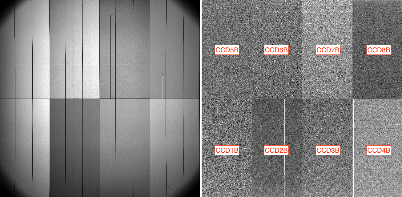
2022-04-23: All CCDs
(B amplifiers) show nominal bias noise and response to
illumination
The following figure shows a flat and a bias frame taken with the B
amplifiers on April 23, 2022. The bias noise and response of
illumination of all CCDs is nominal.
2020-09-15: CCD5B high
bias noise but nominal throughtput
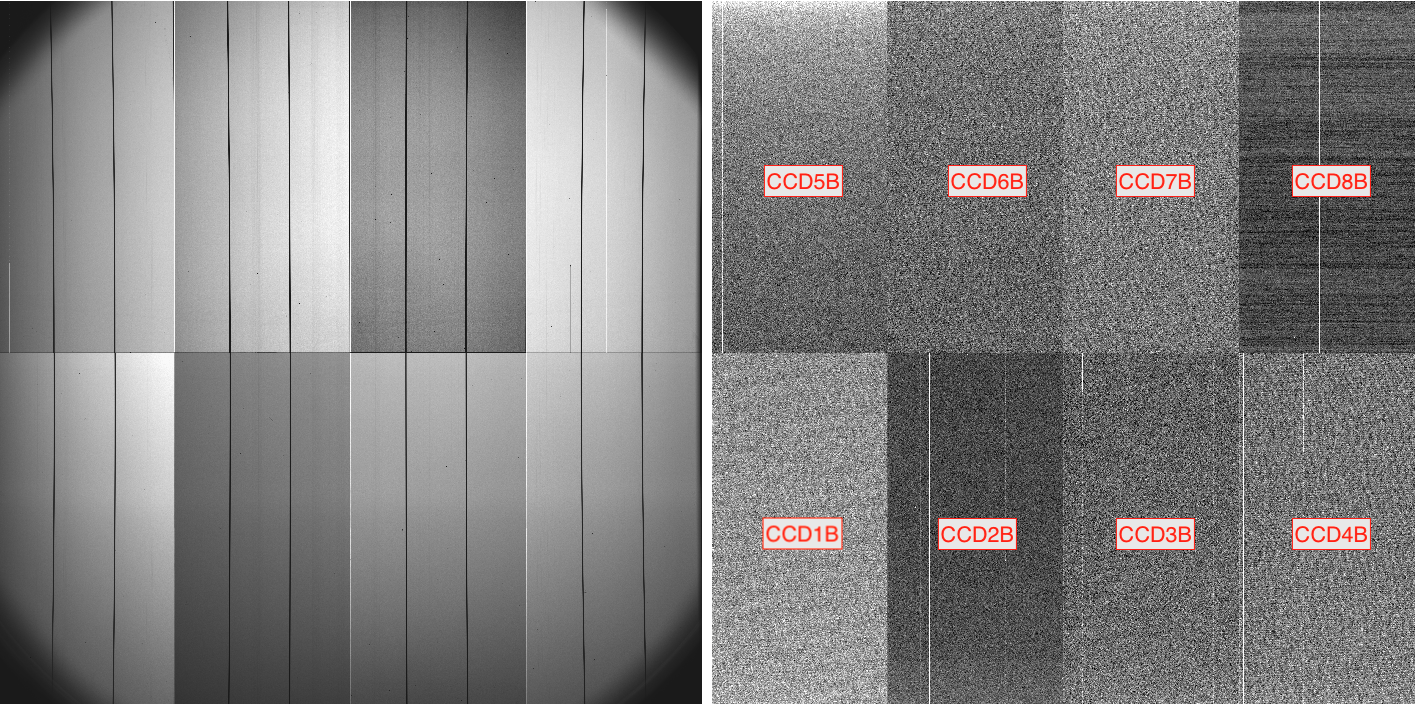
The following figure shows a flat and a bias frame taken with the B
amplifiers on October 17, 2020. The CCD5B bias is noisier the rest
of the CCDs. The flat frame displayed on the left-hand side of the
figure is nominal for all CCDs, including CCD5B. Note also the
horizontal bands on the CCD8B bias.
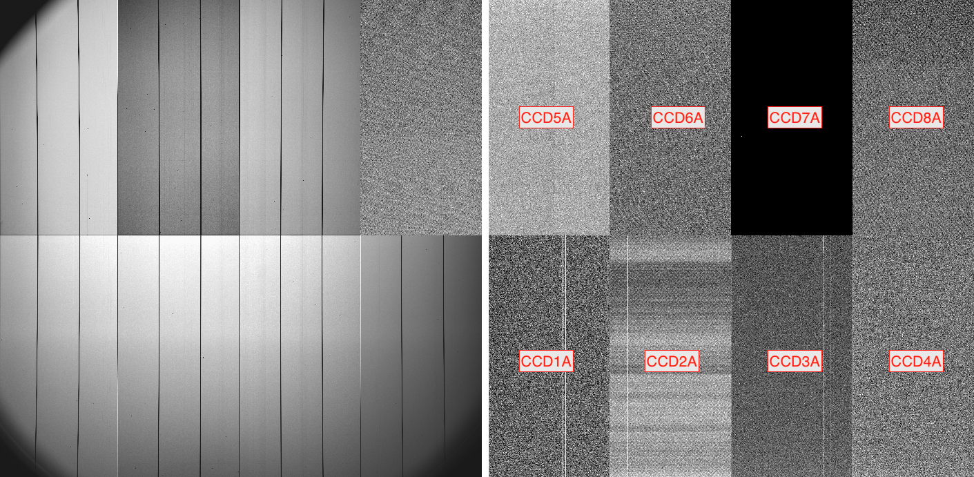
The following figure shows a flat and a bias frame taken with the A
amplifiers on October 17, 2020. The CCD5A bias is nominal, but CCD5A
does not respond to illumination. Note also the horizontal bands on
the CCD3A bias. The CCD6A bias has all pixel values at 1024
counts. The CCD8A flat counts are about half the flat counts on the
neighbor CCDs.
 Due to the various issues on spectra taken with the A
amplifiers, reading out with the B amplifiers is required for DEIMOS
spectra.
2020-02-14: CCD5 bad response to illumination
The following figure shows a flat and a bias frame taken on February
14, 2020. The bias frame on the right-hand side of the figure looks
normal. The flat frame displayed on the left-hand side of the figure
does not contain any signal on CCD5. Therefore, spectra from slits
placed on the the CCD below CCD5, i.e. CCD1, will be missing the red
side of the spectrum.
 As a consequence, placing high priority targets on CCD1 is not
recommended if the spectral features of interest are located on the
red side of the spectrum. Please,
see section on the relative orientation
between the dsimulator diagram and the detector plane to
visualize the location of CCD1 on dsimulator. Alignment boxes placed
on CCD1 will not be affected by the CCD5 issue.


