
Original version - Robert W. Goodrich - 13 Dec 2002
Latest update - Carlos Alvarez - 30 Dec 2024
NIRC2 is a near-infrared instrument designed to take full advantage of the adaptive optics on the Keck II telescope of The W. M. Keck Observatory on Mauna Kea, Hawaii.The Co-PIs are Keith Matthews and Tom Soifer, both of Caltech. The instrument was built by Keith Matthews and engineer Sean Lin of Caltech, with help from James Larkin, Ian McLean, and others at UCLA (detector electronics and related software), and Al Conrad, Bob Goodrich, and Allan Honey at Keck Observatory (software). Support in Waimea was provided by Jim Bell, Randy Campbell, and Drew Medeiros. It was delivered to Hawaii in the spring of 2001, seeing first light in the summer of 2001.
NIRC2 is positioned behind the AO bench on the Left Nasmyth Platform of Keck II. The instrument operates from 1 to 5 µm, providing three selectable cameras to cover the expected range in image sizes. Two filter wheels with 18 positions each provide a variety of filters and/or grisms, while a focal plane mechanism provides slits and occulting spots for coronography. A dedicated slide carries larger grisms for spectroscopy. Six selectable pupil masks are available to reduce background noise sources; four of these rotate in concert with the telescope pupil and one is specific to spectroscopy.The detector is a 1024x1024 Aladdin-3 InSb array with four-quadrant readout into 32 channels.
The light provided by the AO system enters the NIRC2 dewar through a CaF2 window. It then passes through two preslit blades which provide the first level of baffling. These movable blades change position depending on which camera is in use and whether or not a slit is in the beam. The beam comes to a focus where there are two slide mechanisms. The slit slider carries several slits of varying widths. A mask slider beneath it selects which slit provides light to the rest of the instrument. The slit slider also contains a set of coronographic spots. A third use of the slit and mask sliders is to provide a focal plane baffle for imaging through the three cameras. After the slit and mask sliders, the light is collimated.
Beneath the slit is a wheel which provides a selection of pupil masks, including one for spectroscopy, and two rotating masks designed to block light from the spiders as well as the secondary obstruction. Next comes two filter wheels with 18 positions each. Below the filter wheels is a relatively slow shutter, which can be used to close off external light and may also be used to stop an exposure if, for example, the AO system loses lock on a target. The beam next passes through a grism slide, with three slots plus an open position.
Last in the optical path is one of three selectable cameras. These have nominal scales of 0.01, 0.02, and 0.04 arcsec/pixel, matching the expected diffraction performance of the telescope and AO system at different wavelengths (J, K, and M bands, roughly). The cameras focus onto the InSb detector, described in more detail below.
All moving parts in NIRC2 are inside the dewar. The filter wheels and pupil mask are on rotating wheels, while other mechanisms (preslits, slits, coronagraphic spots, grisms, the shutter, and the cameras) are on slide mechanisms.
Cooling is provided by a closed-cycle system similar to that installed on NIRSPEC. Two cold heads provide three stages of cooling, controllable via software. Temperature sensors are provided on the detector head, optical bench, cold shield, and other places in the dewar.
The detector is a 1024x1024 Aladdin-3 array with 27 µm pixels. The detector QE is ~ 80% at 1.7 microns.
The NIRC2 detector electronics was originally based on Transputers. Due to obsolescence concers and potential difficulty to regain detector operation if transputers were to fail, the old electronics was replaced with a STA Archon controller.
The Archon controller was installed in February 2023, but science operations were still based on the Transputers until November 2023. Our testing setup was such that we were able to test the Archon controller when NIRC2 was not scheduled for science, and switch to the Transputers for NIRC2 science operations.
Science operations with the Archon controller started on November 20, 2023. We experienced several issues during the first few months of Archon operations, including transient vertical stripes in the bottom-right detector quadrant and intermittent high detector electronics noise events. These issues were addresses in March 2024 by making new video cables to connect the Archon controller with the detector connector plate and repairing the Archon custom-made PCB. No major detector electronics noise issues have occurred since March 23, 2024.
The main operational changes resulting from the upgrade are:
The Archon controller provides 4 tested readout modes:
The read noise in a CDS readout is 38 electrons. For MCDS mode with up to 64 reads, readout noise drops as the square root of the number of reads. Beyond that the noise continues to drop, although not as rapidly as the square root. It continues to drop to 512 reads, beyond which it has not been tested. Section 2.2 shows the read noise as a function of number of MCDS reads.
The detector is linear to about 10,000 DN. This is the result of a compromise between linearity and dark current.
Narrow- and broad-band filters are provided. The filter complement is given in section 2.1, together with sensitivity and background values to aid in signal-to-noise estimates
Three different cameras provide scales of 0.01, 0.02, and 0.04 arcsec/pixel. These provide good matches to the Keck diffraction size at J, K, and M bands.
Occulting spots can be placed in the focal plane using the slit slide. The spots are opaque areas deposited on a quartz substrate. The spot transmissions are not zero, but have been measured to be 0.12% in both J and H, and 0.22% in K. (These numbers are relatively uncertain.) A variety of spot sizes are available. The following lists their names, with the number after "corona" being the spot size in milliarcseconds:
| corona100 corona150 corona200 corona300 corona400 |
corona600 corona800 corona1000 corona1500 corona2000 |
Additionally, NIRC2 also has two Vector Vortex Coronaghaphic (VVC) masks. There is an L-/M-band optimized vortex mask and a K-band optimized mask. Observations with the vortex require the utilization of a special software called QACITS. Extensive information on the vortex coronagraph can be found in the Vortex Coronagraph User Manual. Detailed information on QACITS can be found in QACITS User Manual. However, please follow the instruction in Section 5.2 to run the observations with the vortex coronograph at night.
Grisms may be installed either in the filter wheel or in a dedicated grism slide. Currently there are two grisms, both in the grism slide. The tables below list various useful parameters for NIRC-2 spectroscopy. The columns are:
|
Camera
|
Filter
|
Order
|
Central
wavelength (microns) |
Dispersion
(Ang./pix) |
Wavelength
range of filter (microns) |
# pixels
to cover range |
Resolving
power per pixel |
|---|---|---|---|---|---|---|---|
|
Narrow
|
J
|
6
|
1.248
|
1.092
|
0.163
|
1490
|
11,430
|
|
J
|
5
|
1.248
|
1.308
|
0.163
|
1250
|
9,540
|
|
|
H
|
4
|
1.633
|
1.628
|
0.300
|
1840
|
10,030
|
|
|
K
|
3
|
2.196
|
2.144
|
0.336
|
1570
|
10,240
|
|
|
Kp
|
3
|
2.124
|
2.144
|
0.336
|
1640
|
9,910
|
|
|
Medium
|
J
|
6
|
1.248
|
2.190
|
0.163
|
740
|
5,700
|
|
J
|
5
|
1.248
|
2.616
|
0.163
|
620
|
4,770
|
|
|
H
|
4
|
1.633
|
3.255
|
0.300
|
920
|
5,020
|
|
|
K
|
3
|
2.196
|
4.113
|
0.336
|
820
|
5,340
|
|
|
Kp
|
3
|
2.124
|
4.113
|
0.336
|
850
|
5,160
|
|
|
Wide
|
J
|
6
|
1.248
|
4.373
|
0.163
|
370
|
2,850
|
|
J
|
5
|
1.248
|
5.236
|
0.163
|
310
|
2,380
|
|
|
H
|
4
|
1.633
|
6.519
|
0.300
|
460
|
2,500
|
|
|
K
|
3
|
2.196
|
8.226
|
0.336
|
410
|
2,670
|
|
|
Kp
|
3
|
2.124
|
8.226
|
0.336
|
430
|
2,580
|
|
Camera
|
Filter
|
Order
|
Central
wavelength (microns) |
Dispersion
(Ang./pix) |
Wavelength
range of filter (microns) |
# pixels
to cover range |
Resolving
power per pixel |
|---|---|---|---|---|---|---|---|
|
Narrow
|
J
|
6
|
1.248
|
0.644
|
0.163
|
2530
|
19,380
|
|
J
|
5
|
1.248
|
0.704
|
0.163
|
2320
|
17,730
|
|
|
H
|
4
|
1.633
|
0.929
|
0.300
|
3230
|
17,580
|
|
|
K
|
3
|
2.196
|
1.267
|
0.336
|
2650
|
17,330
|
|
|
Kp
|
3
|
2.124
|
1.267
|
0.336
|
2770
|
16,760
|
|
|
Medium
|
J
|
6
|
1.248
|
1.288
|
0.163
|
1270
|
9,690
|
|
J
|
5
|
1.248
|
1.407
|
0.163
|
1160
|
8,870
|
|
|
H
|
4
|
1.633
|
1.858
|
0.300
|
1610
|
8,790
|
|
|
K
|
3
|
2.196
|
2.534
|
0.336
|
1330
|
8,670
|
|
|
Kp
|
3
|
2.124
|
2.534
|
0.336
|
1390
|
8,380
|
|
|
Wide
|
J
|
6
|
1.248
|
2.576
|
0.163
|
630
|
4,840
|
|
J
|
5
|
1.248
|
2.797
|
0.163
|
580
|
4,460
|
|
|
H
|
4
|
1.633
|
3.420
|
0.300
|
880
|
4,770
|
|
|
K
|
3
|
2.196
|
5.078
|
0.336
|
660
|
4,320
|
|
|
Kp
|
3
|
2.124
|
5.078
|
0.336
|
690
|
4,180
|
Slits are also available in a variety of widths. A list is given below, where the number after "slit" gives the width in milliarcseconds.
| slit10 slit20 slit30 slit40 |
slit60 |
Note that since the slits and coronagraphic spots are on the same slide, it is not possible to do coronagraphic spectroscopy.
Spectroscopy with NIRC2 is rather different than with many instruments; see section 5.3 for details.
Sounds are handled via the following keywords in the new nirc2plus keyword service:
Each keyword has an associated sound defined in the Eventsounds GUI, which has the following functionalities:

The playsound script has been simplified to emit the sounds corresponding to the SequenceComplete event as follows:
modify -s nirc2plus sequenceip=Yes
modify -s nirc2plus sequenceip=No
Therefore, playsound script can only play the sound assigned to the SequenceComplete event.
Below is a table listing all filters available with NIRC2, including zeropoint and sky estimates (when measured), and the maximum exposure time expected in the narrow-field camera (before the sky saturates).
Table 2.1 Filters, sensitivities,
and background rates
(Clicking on a filter name will bring up a plot of that filter's transmission
curve.)
Filter |
Central wavelength (µm) |
Bandpass |
Cut-On Wavelength (µm) |
Cut-Off Wavelength (µm) |
Photometric |
Sky (mag./ sq. arcsec) |
T(max) (sec) |
Broad Band |
|||||||
1.0311 |
0.0481 |
1.007 |
1.0551 |
||||
1.0180 |
0.0996 |
0.9682 |
1.0678 |
||||
1.248 |
0.163 |
1.166 |
1.330 |
||||
1.633 |
0.296 |
1.485 |
1.781 |
||||
2.196 |
0.336 |
2.028 |
2.364 |
||||
2.146 |
0.311 |
1.991 |
2.302 |
24.53 |
12.2 |
630 |
|
2.124 |
0.351 |
1.948 |
2.299 |
24.74 |
12.2 |
630 |
|
3.5197 |
1.3216 |
2.8589 |
4.1805 |
||||
3.776 |
0.700 |
3.426 |
4.126 |
||||
4.670 |
0.241 |
4.549 |
4.790 |
||||
Narrow Band |
|||||||
1.0847 |
0.0182 |
1.0756 |
1.0938 |
||||
1.096 |
0.016 |
1.088 |
1.104 |
||||
Jcont |
1.2132 |
0.0198 |
1.2033 |
1.2231 |
|||
Pa Beta |
1.2903 |
0.0193 |
1.2807 |
1.3000 |
|||
Hcont |
1.5804 |
0.0232 |
1.5688 |
1.5920 |
|||
CH4S |
1.5923 |
0.1257 |
1.5295 |
1.6552 |
|||
FeII |
1.6455 |
0.0256 |
1.6327 |
1.6583 |
|||
CH4L |
1.6809 |
0.1368 |
1.6125 |
1.7493 |
|||
2.0563 |
0.0326 |
2.0400 |
2.0726 |
||||
2.1686 |
0.0326 |
2.1523 |
2.1849 |
||||
2.1281 |
0.0342 |
2.1112 |
2.1452 |
||||
2.2622 |
0.0388 |
2.2428 |
2.2816 |
||||
Kcont |
2.2706 |
0.0296 |
2.2558 |
2.2854 |
|||
CO |
2.2891 |
0.0267 |
2.2757 |
2.3024 |
|||
H2O |
3.0629 |
0.1549 |
2.9855 |
3.1404 |
|||
PAH |
3.2904 |
0.0555 |
3.2627 |
3.3182 |
|||
3.987 |
0.069 |
3.952 |
4.021 |
||||
4.052 |
0.068 |
4.018 |
4.086 |
||||
The NIRC2 Zero point values were updated after photometric tests in April 2004.
This table shows the zero-point, Z, and sky brightness, S, through various NIRC2 filters, combined with the narrow camera and the circumscribed pupil (the "open" position of the pupil wheel).
The magnitude of the star is Z + 2.5 log10 (counts/sec) - 2.5 log10(Strehl).
Note that the Strehl ratio will vary according to atmospheic conditions (e.g. seeing), the brightness of the AO lock star, and the distance away from the lock star.
The gain, G, is 4.0 electrons/count.
S is the sky brightness in magnitudes per square arcsec. The sky background in counts per pixel is given by:
counts/sec/pixel = (arcsec/pixel)^2 * 10^[0.4*(Z-S)]
where (arcsec/pixel) is the pixel scale, e.g. 0.040 for the wide camera.
T(max) is the maximum exposure time without saturating the background in the narrow camera.
Noise sources include noise in the electronics, statistical noise from the background, and statistical noise from the target itself. Which of these noise sources dominates depends on your observing mode. Bright targets will often be dominated by their own statistical noise, while faint targets may be dominated by background noise. In the thermal infrared (beyond ~ 2.5 µm) almost all observations are dominated by background.
Read noise depends on the readout mode of the detector. In CDS mode it is 38 electrons/pixel. In MCDS mode it drops roughly as the square root of the number of reads until around 64 reads, then drops more slowly until at least the 512-read level. A plot of the read noise vs. number of MCDS samples is shown below:

Figure 2.1 Read noise vs. number of MCDS samples.
Statistical noise from the target and background are simply the square root of the number of electrons recorded from the source.
Dark current is also a function of the number of MCDS samples. This is because every time the detector is read the four on-chip amplifiers glow slightly. This glow shows up as an elevated background and rises in the background in the four corners of the image. The figure below shows the dark current (in DN/sec) as a function of the number of MCDS reads for a 200 sec. exposure. The drop in effective dark currrent above 300 samples is not understood.

Fig. 2.2 Dark current vs. number of MCDS samples (200 sec exposure).
Signal-to-noise can be calculated using estimates of the background rates and the sensitivity through each filter. Keep in mind that the different camera scales must also be taken into account when estimating signal-to-noise. In the background-limited case this is not so important, but in the read-noise limited case it is very important.
Formula to calculate S/N from the read noise, background rate, and sensitivity. Will depend also on which camera is in use.
      Total elapsed observing time(sec) = 6*(ndither+1) +
      12*ndither*nframes + ndither*nframes*coadds*(itime +
      tread*(nread-1))
where:
6 sec is the AO overhead during dither (open loops, move telescope, reposition Field Sterring Mirrors (FSMs), reposition WFS focus (FCS), close TT loop, close DM loop).
12 sec is the time to read and write a NIRC2 image including FITS information.
an additional overhead of a few seconds (<5-10 secs) may occur, maybe once every 20 dither moves, when repositioning the FCS or the FSMs.
All these numbers have been checked real data and observing logs:
Note: It is sometime necessary to work in 512x512 when the background is higher given the short inetgration time for Lp and Ms.
Given the longer integration time, we will run in MCDS mode:
A number of planning tools are available, both over the Web and locally in Waimea. In particular the SKY program can be used to verify finding charts, locate potential AO stars, and overlay the DSS on your field. A Web-based version of SKY is in the works to allow you to run it from outside Waimea.
The starlist format is relatively simple:
You can add any of the following optional tokens identified by a keyword (no spaces are allowed around either side of the equals sign):
There should be no blank lines in the file, including at the beginning or end.
Examples:
197+17.1        07 29 09.400 +20 54 45.90 2000.0
ring neb        18 53 36.000 +33 02 00.00 2000.0
SAO 102961      17 34 24.13 11 52 28.29 1950.0 pmra=+0.0001 pmdec=-0.007 vmag=9.0
HD 19904        03 08 49.1  -39 14 24       1950
G77-31          03 10 40.5  +04 35 12       1950 pmra=0.1139 pmdec=0.107
Hale-Bopp 5hr   17 30 6.62  -4 41 58.4 APP dra=0.35 ddec=7.3
Titan   6:00UT  01 05 39.6050 +04 00 28.846    APP dra=-0.96 ddec=-4.2
Once you have created your starlist, double check to make sure there are no blank lines in it. Then transfer it to /kroot/starlists/xxx, where "xxx" is your name. (New observers may have to create their own subdirectory under /kroot/starlists.) The /kroot/starlists directory should be visible from every Keck computer.
If you observe from the Keck HQ in Waimea, you will be sitting in front of a remote computer, typically hanauma in RemoteOps II. The instrument computer is named waikoko and is on the summit. The VNC server is named vm-nirc2 (a.k.a nirc2) and is a virtual machine also located on the summit. Part of the instrument-related software runs on waikoko and part runs on vm-nirc2. Almost all instrument-related commands must be typed into a vm-nirc2 xterm.
In general when you log into waikoko or bring up a waikoko xterm from the OpenWindows menu the software will try to set your DISPLAY environment variable using the "rdisp" command. If this fails you can always set your display by typing "setenv DISPLAY hanauma:0.1", for example.
From the pull-down menu, under "NIRC2 Observing", select "*** Start NIRC2 Software".
Or from a waikoko command line, type "nirc2 start all".
Either of these should bring up a window for commands, a status window showing the most generally useful NIRC2 parameters, a "log tail" containing the log file, and the QuickLook IDL window. The software will also check the health of the software, try to fix things that are not running or are running improperly, and assign you a data directory. (Look in the Status Window for the directory path, or type "runname" once the software is running.)

Figure 3.1 The NIRC2 status display.
If problems arise during the night, you may wish to restart some subcomponent of the software. Under "NIRC2 Observing -> Subcomponents" are various options, or you can often use "nirc2 restart xxx" where "xxx" is the subcomponent ("quicklook", "server", "motors", etc.). Type "nirc2 help" to show the options available with the "nirc2" command.
There are numerous commands for NIRC2, but many of them are considered engineering commands, others are low level commands used by higher level commands, and still others are expected to be rarely, if ever, needed by the observer. Here we give only the most common commands; see Appendix 7.4 for a full, alphabetical list.
An important part of the system is the "help" command. This command is multi-featured. If you type just "help" you will get a description of the tool, and a list of categories of commands. If you type "help cat", where "cat" is one of the categories, you will get a list of NIRC-2 commands with a brief (generally one-line) description of each command within that category. If you type "help command" you will get a more verbose description of the command, its arguments, and its function. If the command is an alias, it will be reported as such. If the command is a shell command, or some other command within the path, the program will attempt to access a UNIX "man" page for the command.
| coadd [n] | Sets the number of coadds to n. If n is not specified, the current value is returned. Note that the data numbers in the resultant image will be the sum of all coadded frames (i.e., the data are not scaled by the number of coadds). |
| nsamp [n] | Sets the number of samples in MCDS mode to n. If n is not specified, the current value is returned. |
| sampmode [type [n]] | Sets the sampling mode to one of: single, CDS, or MCDS. (CDS = correlated double sampling; MCDS = multiple correlated double sampling.) An optional integer in MCDS mode specifies the number of samples (similar to "nsamp" above). If no arguments are given, the current mode is returned. |
| subc nx [ny] | Defines a centered subarray, either nx x nx or nx x ny in size. Note that only centered subarrays are available. Also nx and ny cannot be arbitrary. However, the program will take your request and give you the next largest valid subarray if your request is not valid. |
| shutter [open/close] | Opens or closes NIRC2's shutter, or reports its status. |
| tint [t] | Sets the integration time to t seconds. If no argument is given, the current setting is returned. |
The command "filt ks" will insert the "ks" (K-short) filter, for example.
| frame [n] | Sets the frame number for the next file to n. If no argument is specified, the current frame number is returned. Note that the fileovwr keyword must be set to 1 for this command to overwrite existing files. Otherwise the next file written will have a number one larger than the largest number in the current sequence, independent of the setting of FRAMENO. |
| goi [n] | Takes an exposure, writing it to your data directory. If n is specified, nsequential exposures will be taken. (See also movie for taking exposures at a timed interval.) |
| goibuf [n] | Takes an exposure to "buf1.fits" in the /scratch directory. If n is specified, n sequential exposures will be taken. (At the end /scratch/buf1.fits will contain only the last.) buf1.fits can be used along with buffer math and the other buffers to maintain sky frames, keep coadded images, etc. |
| newdir [disk] | Creates a new directory in the specified disk, or on the disk with the most space. The directory name consists of the disk, e.g., /sdata900, the user, e.g. nirc19, and the UT date of the night's observing, e.g. 14nov02; hence, /sdata900/nirc19/14nov02/. |
| snapi [n] | Takes n sets of image pairs, one on the target and one offset by the nod parameters (see nod). If n is not specified, only a single pair of exposures is taken. |
| test [n] | Takes n (n=1 by default) test exposures (written to /tmp/TEMPFITS). |
Note that for exposures which are calculated to last longer than 60 seconds, a countdown timer will appear to help you keep track of the exposure progress.

Figure 3.2 The exposure countdown timer, "xcount".
Another tool that can control exposures and give feedback on their progress is the "nirc2exp" GUI.
| bstat [n] [xs ys xe ye] | Shows statistics on buffer n (n=1 by default). If [xs ys xe ye] are specified, the corresponding subregion of the image is analyzed, not the entire image. |
| bufN = bufM[ {+,-,x,/} bufL] | Copies buffer M to buffer N, or if an operation and a third buffer are given, performs the math and places the result in buffer N. For example, the command "buf3 = buf1 - buf2" takes /scratch/buf2.fits, subtracts it from /scratch/buf1.fits, and places the result in /scratch/buf3.fits. "buf8 = buf9" simply copies /scratch/buf9.fits to /scratch/buf8.fits. |
| dir | Lists data images in the current data directory. |
| dp [n] | Displays either file n or the last file (if n is not specified). |
| dpname file | Displays the named file. Note that in general the full path to the file must be given. |
| odiff | Displays the next-to-last frame minus the last frame (see also sdiff). |
| pdiff m n | Displays frame n minus frame m. |
| pstat n [xs ys xe ye] | Displays statistics from file n. If [xs ys xe ye] is specified, only that subregion will be analyzed. If n is not specified, the last frame will be analyzed. |
| sdiff | Displays the last frame minus the next-to-last frame. (Has the opposite sign from odiff.) |
| wd n | Writes buffer n into your data directory. |
There are ten blocking coronagraphic slits available. Type "corona x" where "x" is the size of the spot in milliarcsec.
| corona 100 corona 150 corona 200 corona 300 corona 400 |
corona 600 corona 800 corona 1000 corona 1500 corona 2000 |
When the spot is inserted, the script will tell you what row to expect the spot center.
You can also send the spot to a column other than the center, e.g. "corona 300 700" to send the 300 milliarcsec slit to column 700. The row number may be slightly different.
When you insert a spot using the medium or wide cameras, adjacent spots will also show up in the field of view. Do not get them confused with your intended spot, which should go to the requested column (generally the field center). Dirt on the slide containing the spots will also show up.
There are also two vortex coronagraphic masks. The approximate location each of the mask centers on the NIRC2 detector when used in full frame are:
| vortexk | [528,545] | K-band optimized mask |
| vortexlm | [543,498] | L-/M-band optimized mask |
The command to insert the vortex masks in the optical path is "vcorona". For instance, to insert the L-/M-optimized vortex mask, the command is "vcorona vortexlm".
Spectroscopy is somewhat complicated with NIRC2. Refer to section 5.3 for details. In general you will use the higher level scripts in the manner described in that section, rather than lower level commands like "sgr". Grism information can be found in tables 2.2 and 2.3.
There are two commands:
| lamp name [on/off] [y/slit] | Turns on or off the specified lamp. If no argument is given, the current state of the lamp is returned. If "slit" is specified, the lamp will be moved to the position in the focal plane corresponding to the current slit position. If a floating point or integer value is given, the lamp will go to that row number with the current camera. |
| lamps [off/stow] | Either turns all the lamps off or stows the lamp stage out of the beam. |
| endnight | Puts the instrument into "safe" mode at the end of each night's observing. |
| help [command] | Prints out a set of brief help instructions for the specified command. Note that an attempt is made to distinguish between commands that are aliases, NIRC-2 commands, or other (including UNIX) commands. "command" can also be one of several "categories" of commands. In that case a list of NIRC-2 commands in that category is printed, together with a (usually one-line) description of each command. |
| loadstate [type] [file] | Reads a configuration stored in the specified file and sets the instrument accordingly (see savestate). |
| obj [str] | Sets the "OBJECT" keyword to "str". If no argument is given, returns the current value. |
| observer [str] | Sets the "OBSERVER" keyword to "str". If no argument is given, returns the current value. |
| user [-d] name | Adds the path /home/nirc2eng/vis/name to the PATH variable, allowing users to access their own scripts. Note that this path is added to the front of the PATH variable, meaning that if users have their own version of "goi", for example, it will be used rather than the facility goi script. If "-d" is specified before the name, the directory is deleted from the PATH variable and those scripts are hence made unavailable. |
| savestate [type] [file] | Reads the current instrument settings and records them in the specified file.type information. The three types are: det, env, mot, referring to detector parameters such as integration time, coadds, sampling mode, etc., environment parameters such as frame number, object name, output directory, etc., and motor parameters such as the camera, filter, etc. If no type is specified, all three parameter sets will be read. If no file is given, the default name of $HOME/.state will be assumed. |
| skey | Lists all NIRC2 keywords. |
| showtemps | Shows the NIRC2 temperatures. |
A number of commands provide interaction with the telescope and adaptive optics systems. Two tables are presented: a list of commands for general telescope moves, followed by a list of dither commands. Note that there are various coordinate frames: astronomical (N, E, S, W, etc.), az/el, instrument coordinates, and guider coordinates. There are also different units: arcsec or pixels. Similar commands are grouped together.
|
E e N n S s W w en e n |
Moves the telescope e arcsec east, n arcsec North, s arcsec South, w arcsec West, or (e,n) arcsec East and North. |
|
az a azel a e el e |
Moves the telescope (a,e) arcsec in azimuth and elevation. |
| cent x y | Moves the telescope so that a target seen at (x,y) moves to the center of the image. |
| dfoc df | Changes the telescope focus by df millimeters. |
| foc [f] | Changes the telescope focus to f. If no argument is given, returns the current telescope focus. |
| focAO f df [Nsteps] | Focus AO by starting at focus f, and making Nsteps steps of df each. Nsteps must be 10 or less, and defaults to 5. The resulting image stacks slices from each focus image, showing the progression of image size with focus. |
| fromsky | Offset the telescope by the opposites of the nod parameters (see tosky and nod). |
| gomark | Return to a previously stored telescope offset (see mark). |
|
gx x gxy x y gy y |
Move the telescope (x,y) arcsec in guider coordinates. |
| mark | Stores the current telescope offsets (see gomark). |
| mov x1 y1 x2 y2 | Move an object from (x1,y1) to (x2,y2) on the detector. |
| nod e n node e nodn n |
Set the nod parameters to e arcsec East and n arcsec North. These parameters are used to specify the sky position for snapi and fromsky/tosky commands. |
| px x pxy x y py y |
Move the telescope (x,y) pixels in the detector coordinates. |
|
rotate x rotate x posang rotate x vertang |
Set the AO rotator mode and angle. In posang mode, a value of 0 specifies North-up on NIRC2. In vertang mode, a value of 0 specifies zenith-up on NIRC2. The rotator mode defaults to posang if omitted. |
| scent x y | Move the telescope to center an object at (x,y) on the slit. |
| tosky | Offset the telescope by the nod parameters (see fromsky and nod). |
| x x xy x y y y |
Move the telescope (x,y) arcsec in the detector coordinates. |
| zero | Returns the telescope to the zero offset position. |
| box5 | A 5-pt dither pattern using the nod parameters as the "leg size." |
| box9 | A 9-pt dither pattern using the nod parameters as the "leg size." |
| bxy5 x [y] | A 5-pt dither pattern in the detector coordinate system. The leg size is x arcsec by y arcsec. If y is not specified, it is assumed equal to x. |
| bxy3 x [y] | A 3-pt dither pattern in the detector coordinate system. A bxy3 is basically a bxy5, but with the the lower left and central positions omitted. Due to elevated noise in the lower left quadrant, this has become the dither pattern of choice for many observing programs. |
| bxy8 x [y] | An 8-pt dither pattern in the detector coordinate system. The leg size is x arcsec by y arcsec. If y is not specified, it is assumed equal to x. A bxy8 is basically a bxy9 without the central position. |
| bxy9 x [y] | A 9-pt dither pattern in the detector coordinate system. The leg size is x arcsec by y arcsec. If yis not specified, it is assumed equal to x. |
| dither file [Xscale [Yscale]] | A general dither pattern routine, reading the pattern from file. Optionally, the pattern in the file may be scaled but (Xscale,Yscale). If Xscale is specified by not Yscale, the latter is assumed equal to Xscale. See section xxx for a description of the file format for dither. |
| sp2 dy [n] | Dither along the slit in two positions separated by dy arcsec. An optional parameter allows you to repeat the pattern n times. |
| sp5 dy [n] | Dither along the slit in five positions separated by dy arcsec. An optional parameter allows you to repeat the pattern n times. |
| sp7 dy [n] | Dither along the slit in seven positions separated by dy arcsec. An optional parameter allows you to repeat the pattern n times. |
| wide5 | Take data in a wide, 5-point dither pattern. |
A small number of commands allow interaction with the AO system. Note that some of the AO interaction will be via the AO GUIs themselves. The AO commands that you most likely will need to know are:
| aohatch [open,closed] | Opens or closes the AO hatch, or reports its current state. |
| wait4ao [on,off] | Turns on or off the wait for: DAR correction, tip-tilt lock, and deformable mirror (DM) lock. With no argument, it returns the current state. |
| bxy5 x [y] | A 5-pt dither pattern in the detector coordinate system. The leg size is x arcsec by y arcsec. If y is not specified, it is assumed equal to x. |
| bxy8 x [y] | An 8-pt dither pattern in the detector coordinate system. The leg size is x arcsec by y arcsec. If y is not specified, it is assumed equal to x. A bxy8 is basically a bxy9 without the central position. |
| bxy9 x [y] | A 9-pt dither pattern in the detector coordinate system. The leg size is x arcsec by y arcsec. If yis not specified, it is assumed equal to x. |
| dither file [Xscale [Yscale]] | A general dither pattern routine, reading the pattern from file. Optionally, the pattern in the file may be scaled but (Xscale,Yscale). If Xscale is specified by not Yscale, the latter is assumed equal to Xscale. See section xxx for a description of the file format for dither. |
| mosaic Nx Ny dx dy | Mosaic Nx by Ny positions, separated by dx in detector x coordinates and dy in detector y coordinates. |
| sp2 dy [n] | Dither along the slit in two positions separated by dy arcsec. An optional parameter allows you to repeat the pattern n times. |
| sp5 dy [n] | Dither along the slit in five positions separated by dy arcsec. An optional parameter allows you to repeat the pattern n times. |
| sp7 dy [n] | Dither along the slit in seven positions separated by dy arcsec. An optional parameter allows you to repeat the pattern n times. |
| wide5 | Take data in a wide, 5-point dither pattern. |
As an example, you may want to take some test images during the afternoon of your run to make sure the detector is healthy and you understand how to use the interface. The sequence below closes the NIRC2 shutter. It then sets some detector parameters, takes a series of images, displaying the first image difference. Integration time and coadds are then changed again, more data taken, etc. Note that for longer integrations time the sampling mode is changed to MCDS with 32 reads. Here is the command sequence:
dark
tint 1
coadd 30
goi 2
sdiff
goi 8
tint 2 ; coadd 15
goi 10
tint 10 ; coadd 1
goi 10
tint 600
sampmode 3 32
goi 5
Note that a semicolon on a line separates two commands. As another example, the same observer may use the following sequence to observe a star in a couple of different filters:
filt k ; tint 10
obj HD 1234567, The Gnarly Star
bxy5 2
filt h
tint 8
bxy5 2
A 5-point dither pattern in the K filter with 10 s integrations is taken, followed by the same pattern with 8 s images through the H filter.
When you take an exposure, there are certain things that you would like to be sure of. For example, you typically don't want to take an exposure while motors are still in motion. The NIRC-2 motor commands generally return to the command line before the motor is in position, to allow fully parallel motor moves. When observing a star, you don't want to take an exposure without the AO locks being on and stable. With the NIRC-2 software, this is all taken care of within the "goi" and "test" exposure commands. Since variations of these commands, such as "goibuf," actually call "goi" or "test," these two commands form a natural place to implement such checks. Also, in principle you probably don't care whether motors are in place and AO systems locked unlessyou are taking an exposure.
So what does "goi" do before it actually starts an exposure? Some of what happens is controllable via other commands, in particular on the AO side, since some types of observations do not want to lock AO, and some do, etc. When you type "goi" (or "test"):
This all means that, assuming the AO wait parameters are all set appropriately, you can start a new exposure before NIRC-2 motors have gotten into position, and/or before the AO system has finished locking on the target.
The AO waits for tip-tilt, deformable mirror, and FCS all have timeouts associated with them, so that the command will not hang indefinitely. These timeout periods are set rather high, however, so you may think that the command has hung.
A typical "goi" command might show output such as this:
(example goi output)
The image display GUI is known as "QuickLook," and will be familiar to NIRSPEC observers. In general it will automatically display images as they are taken, with one important caveat. During rapid sequences of images some may be "skipped," as the software tries to keep in step with the data flow. You can also send images to the display through the command line.

Figure 3.2 The QuickLook image display and analysis tool.
The QuickLook GUI itself has a number of important observing features, including allowing observers to make small telescope moves, measuring the Strehl ratio on images, and displaying pair-subtracted images. Here we only touch on the most commonly needed features.
Note that one problem that QuickLook has is inteference between different windows. So when you pop up a window to perform one function, such as making a line cut or fitting a Gaussian, it is highly advised to dismiss those windows before performing another function. In particular, telescope moves may not work properly with other windows up.
Choose →Open...
Pan by clicking on the "Center" button at bottom left. Then click on the desired center of the image. You can zoom in or out by using the Z+ and Z- buttons.
Choose Disp →Set Display Parameters, or Disp →Autoscale, etc. You can change the color mapping in the current scaling by clicking and dragging with the right mouse button on the image itself. Note that it is very easy to invert the sense of the color map (so that brightly colored pixels are actually lower in value than dark pixels). Also note that once you select a different display option you may have to click Disp →Redisplay to get it to take effect.
To return to the default scaling and color display, click Disp → Reset Display Parameters.
Choose Math& → Arithmetic...
You can select two files for the operation, and an arithmetic operator. Note
that selecting ``Current" for a file will use whatever image is currently
loaded into the display. This allows one to, for example, take an image, subtract
a bias, divide by a flat field, etc., all within QuickLook, by performing
the operations one at a time.
Choose Tel → Move telescope
This will prompt you to click on the current position of an object in the
image, and then the position where you would like the object to end up. Note
that if you accidentally start this process you still need to follow each
step; there is not an elegant way of canceling the move.
Choose Plot → Gaussian Fit
Another window pops up and the cursor turns into the box with a dot in the
middle. Click the left mouse button on the position of a stellar image (or
whatever you are trying to fit a Gaussian to). The Gaussian parameters will
be calculated using the image within the box defined at the bottom of the
Gaussian Fit window. These can be changed if needed.
Choose Math → Statistics
The region over which the statistics is calculated is shown in the numbers
at the bottom of the screen. You can type your own numbers into these boxes,
or you can click and drag the left mouse button on the image to define an
area. The mean, median, mode, maximum pixel, minimum pixel, and standard deviation
are calculated and displayed.
Choose Math → Strehl
A Strehl window will pop up. Make sure that the appropriate wavelength is
entered in the relevant box. Click on the star image and then on the "Calculate
Strehl" button. Note that in the image window that pops up, comparing
the actual image with an ideal image, there are two Strehl values reported
in the bottom of the window. One of these, labeled "Strehl" is also
reported in large digits in the main Strehl window. The other one, labeled
StrehlAB, seems, however, to be more robust when there are hot pixels present,
and you may want to trust this value more.
When calculating Strehl it is probably a good idea to use a background-subtracted image. This gets rid of bad pixels better than a simple CDS or MCDS image, and empirically produces more robust Strehl estimates.
There is some minor amount of customization that you can do to your environment. There is, of course, much you can do using UNIX to customize your environment, but we must advise against changing the fundamental files like .cshrc, .login, etc. Changing these can affect the behaviour of NIRC2 commands, making the software useless.
There are also some small parameters that you can change. For example, the environment variable XCOUNT_TRIGGER tells the image commands goi and test when to pop up a countdown timer. By default this happens for 60 second exposures, but if you want to change it, e.g., to 30 seconds, you can type "setenv XCOUNT_TRIGGER 30" into the command window. Then any imaging commands that are typed into that window and that are expected to take longer than 30 seconds will trigger the xcount timer.
One of the most powerful features of the NIRC2 software is the ability to easily write your own, custom observing scripts. At the simplest level this merely requires being able to use a UNIX editor. More complicated scripts can perform looping, conditional branching, error trapping, etc., even to the point of calling external IDL, C, or other programs to perform very complex calculations. Scripts can also be based in other languages, for instance IDL, and run NIRC2 commands using some shell command similar to "spawn" in IDL.
First things first! You need to know where to put the scripts. There are two places that you can use. One is considered a long-term storage area: ~nirc2eng/vis. Type "cd ~nirc2eng/vis" on the nirc2 computer. Type "ls" to see what subdirectories already exist. If you have a subdirectory there you can place new scripts into it. The first time through this process you will need to create your own subdirectory. Use your initials or name or some other text that distinguishes your directory from the others in ~nirc2eng/vis. Create the directory by typing "mkdir xxx" where "xxx" is your chosen text. Go into that subdirectory: "cd xxx". Now you can edit your script file or copy one from an outside source.
To put your UNIX directory into the "path," where UNIX will find it, type "user xxx". This will add "~nirc2eng/vis/xxx" to the UNIX PATH environment variable, and do a "rehash" command to make sure all of the executable files in that directory are known.
Another place you can put your scripts is in your home directory's "setups" subdirectory. This area is more appropriate for temporary scripts, since the directories are wiped clean for each new observer.
A third repository is, at HQ, /kroot/visitors. This is an unmanaged area that observers can use to store observing scripts, data reduction tools, etc. Be forewarned, however, that you should not use up too much disk space on this disk, since it is unmanaged, If any observer stores hundreds of MB of FITS images on the disk, for example, we will be forced to "manage" it by arbitrarily deleting large files!
At the most basic level, if you find yourself repeating a series of commands over and over, you can write those commands into a file. Then, typing the name of that file will invoke the commands. For example, the observing sequences described in section 3.3 could easily have been written into a file and run with a single command. One important point; to get your file to look like a command from the UNIX point of view you need to give yourself (at least) "execute" privileges. Do this by typing
chmod a+x filename
rehash
where filename is your script file. The "rehash" just tells UNIX to look around for executable files in its PATH. (Remember to do a "user xxx" command to put your subdirectory in the PATH to begin with!)
You can also pass arguments into your script. Most of the facility scripts accept arguments, and they can be used as examples. In fact, you are highly encouraged to look at facility scripts to get ideas on how to write more efficient scripts.
Finally, there are some facility scripts that might make life easier for you:
| math x [+,-,x,/] y | Returns the value of the expression supplied.
x and y can be either constants (as in "set
value = `math 0.134 x 5`), or variables (as in "set
value = `math 2 + $var1`"). Note that generally you will want
to either print or set the results of the calculation. In the examples
above the "set"
command has been used to set the "value"
variable to the results of the calculation. Note the backquotes surrounding
the math command; these
tell UNIX to execute the math command and return its output to the "set"
command. Note that "math" is a wrapper around the UNIX "bc" command. Type "man bc" for a description of all of the capabilities of the command, which include trig functions, log commands, etc. Also note that "math" works strictly on scalars; it does not do image arithmetic. There are some facility scripts that do arithmetic on buffers, but in general any sophisticated image manipulation is better done in IDL, IRAF, or some other image processing package. |
| pause [text] | Pause the script and (optionally) print out the specified text. You will not get the command line back within the window running the script, as it will sit and wait until you hit <RETURN> in that window before proceeding. But you can type other NIRC2 (or telescope, or AO, etc.) commands into other windows connected to the nirc2 computer, or you can perform other tasks before proceeding. |
To write more complex scripts please refer to the detailed writeup on the Web. As before, using a facility script as a template or example will help, and you may want to have a book on UNIX handy.
Note that a good way to build up complex UNIX commands is to start from
the "inside" and work out. For example, a command used in the "disks"
script is
df -k | grep " /sdata" |
awk '{print $6, $4," (",$5,")"}' | sort -t" "
-1 +1 -nr | sed -e "s/ / /"
You can figure out how to use this command, and make sure that you have all
of the quote types correct and in the right places, by starting with df
-k , then trying df -k | grep
"/sdata" to see if it does what you think, etc., until you
build up the entire command. Then you can paste the command into your
script.
And don't overlook the utility of "echo" statements in strategic parts of your script when you are trying to test and debug the scripts.
From the pull-down menu, choose "*** Shutdown NIRC2". This will make sure that the lamps are off, the shutter closed, and will kill most of the GUIs and xterms showing things like the NIRC2 log file. (Some GUIs may not be killed, because there may still be some use of them after observing has ended.)
From the command line, type "shutdown_nirc2".
Note that QuickLook will not be killed. It is assumed that you may be using QuickLook for data analysis even after you are done using the NIRC2 instrument. You can either kill QuickLook separately or simply log out, which will accomplish the same thing.
Within the OpenWindows desktop menu there will be a submenu labeled "Telescope tools...". Within that submenu you should find the following:
This submenu contains commands to start and stop a guider eavesdrop. Currently only one eavesdrop can run at a time. Highlighting the submenu name itself and releasing will activate the default command, which will bring up the guider eavesdrop. Note that the visible windows have an associated invisible process, which will not get cleaned up if you simply quit all of the windows at the end of the night. Please use the "Stop eavesdrop" item on the submenu to shut down all eavesdrop processes.
Short for "FACilities SUMmary," FACSUM shows relevant telescope parameters, such as RA, Dec, az, el, UT date and time, airmass, secondary focus, and so on.
Arrows showing North and East, or azimuth and elevation, are available for two coordinate systems: the detector (instrument) and the guider. Make sure that you put the compass rose relevant to the detector near the image display, and don't confuse it with the guider rose. The instrument rose is labeled "tkrose (i)" and the guider rose "tkrose (g)". A guider compass rose should pop up when the guider eavesdrop is selected.
There may be a number of "xshow" displays, for text versions of the telescope or AO parameters, for example. "xshow" is a tool for monitoring keyword values.
There is a tool that graphically shows the wavefront sensor counts as a function of time. This cann be especially useful on nights with variable cirrus. It also allows a quick view of the count level for each object.
The main concerns in imaging mode are image scale or field of view, filters, exposure times, and dither patterns.
Use the "camera" command to select one of the three cameras in NIRC2.
Table 5.1 Camera options
|
Camera
Name(s) |
Scale
(arcsec/pixel) |
Field of view
(arcsec x arcsec) |
Band in which
diffraction size matches 2 pixels |
|
wide
cam04 0.04 |
0.04
|
40x40
|
M
|
|
medium
cam02 0.02 |
0.02
|
20x20
|
K
|
|
narrow
cam01 0.01 |
0.01
|
10x10
|
J
|
Note that the camera command will take different names; it might be easier for you to remember the pixel scale rather than the relative field size, for example.
Also note that the medium-field camera has significant field curvature, hence image quality across the entire field suffers. It is possible to achieve high image quality for point sources, however.
For imaging, when a new camera is selected, the appropriate masks in the slit and slitmask slides are automatically put into place.
The corona command will place the requested coronagraphic spot in the center of the field of view. It will also tell you what row the spot should be centered on. In the medium and wide field cameras, centering one spot will also place adjacent spots in the field of view; don't get them confused with your desired spot!
You can also command the spot to a different column, e.g. "corona 300 700" will place the 300 milliarcsec spot at column 700. The row value may be slightly different, since the slide does not move exactly along rows.
The "center" actually differs very slightly from camera to camera:
Table 5.2 Camera centers
|
Camera
|
"Center"
|
|
wide
|
|
|
medium
|
|
|
narrow
|
|
The Y-position of the spots vary from spot to spot as well. The ccent x y command will read both the Y-value of the current spot and the X-value and center a star at (x,y) to these coordinates. The Y-positions of each spot in each camera are:
Table 5.3 Y-positions of coronagraphic spots
|
spot
size |
camera
|
||
|
wide
|
medium
|
narrow
|
|
|
100
|
|||
|
150
|
|||
|
200
|
|||
|
300
|
|||
|
400
|
|||
|
600
|
|||
|
800
|
|||
| 1000 | |||
| 1500 | |||
| 2000 | |||
Note that dirt on the slide containing the spots will also show up. These can be seen by looking at a flat field or sky, and shifting the coronagraphic spot a small amount between exposures.
Note: A new hair-like feature has been detected on the corona600 mask (see images below). The feature apeared after the high-contrast imaging upgrade on March 2019. Thanks to Brendan Bowler (UT Austin) for pointing this out and to Adam Kraus (UT Austin) for providing the images below. The hair-like feature will be removed the next time that the NIRC2 dewar is opened.

|

|
| Narrow-camera flat-field image taken with the corona600 mask and the Kp filter on July 5, 2019. | Ratio of flat-field images taken with the corona600 mask and the Kp filter on June 10 and July 5, 2019. |
We recommend observers using the corona600 mask to take flats with and without the mask to divide out the hair-like feature.
This section describes the basic procedure to perform observations with the vortex coronagraph. Part of the information included in this section is based on the checklist to observe with the vortex coronagraph kindly provided by G. Ruane (JPL) and other members of the vortex development team led by D. Mawet (Caltech).
The commands used to perform the observations are slightly different depending on whether the Shack-Hartmann (SH) wavefront sensor (WFS) or the Pyramid wavefront sensor (PyWFS) is used. The procedure specifies when a command can only be used with the SH WFS or the PyWFS.
Important note: NIRC2 operations require two different computer hosts:
itest due to naming
conflict with Linux O/S built-in command
test.
You can jump straight to any of the sections of the procedure with the following links:
The vortex operation software, QACITS, will take care of centering the star on the vortex masks once an observing sequence is started. Therefore, there is no need for the AO system to correct for the Differential Atmospheric Refraction (DAR) between the AO guide star and the science target.
We recommend running the vortex observations using a new pupil stop optimized for coronagraphy that was installed on NIRC2 during the 2019 upgrade. The software name for this pupil stop is fixedhex. To insert this pupil stop in the optical path use "pupil fixedhex". This stop is not connected to the pupil mask rotator. Hence, the state of the pupil mask rotator (PMR) is irrelevant in this case. The only way to ensure that the fixedhex stop mask matches the telescope pupil is to set the AO rotator to a vertical angle mode of 3.73 degrees:
rotate 3.73 vertang
Note that setting the rotator angle needs to be done before acquiring the target. Therefore, please, let the Observing Assistant know that you will change the rotator angle before she/he acquires the target.
If you decide to take an optional pupil image, please let the Observing Assitant know that she/he does not need to close the AO loops once the target is placed on the NIRC2 pointing origin.
The fixedhex pupil mask is fixed with respect to the detector plane. Hence, there is no need to take a pupil image to check if it is aligned with the the telescope pupil. However it is important to check that the rotator mode and angle are correct, once the rotator is tracking. The Facility Summary GUI (FACSUM) should show the following values:
While the Observing Assistant is closing the AO loops, you can configure NIRC2 to take an image of the star with the narrow camera. The integration time may vary with respect to the examples shown below depending on target brightness. Ideally, you would like to use an integration time that allows you to see the PSF peak but does not saturate excessively (non-lineariy starts at 5,000 counts per coadd). If the target is bright and you are observing with the Lp filter, it might not be possible to avoid saturation. This is OK as soon as you can see a well defined star center.
	  object [your target name here]
	  subc 1024
	  coadd 1
	  sampmode 2
	  tint 0
	  filt lp (or filt ms)
	  vcorona vortexlm
	  pupil fixedhex
	  grism clear
	  camera narrow
	  wait4ao on
	  wait4dar off
	  shutter open
	  object [your target name here]
	  subc 1024
	  coadd 1
	  sampmode 2
	  tint 1
	  filt kp (or filt ks)
	  vcorona vortexk
	  pupil fixedhex
	  grism clear
	  camera narrow
	  wait4ao on
	  wait4dar off
	  shutter open
Once the AO loops are closed and the NIRC2 setup is complete, you can take an image by executing the command goi.
The position of the vortex masks may vary slightly (1 or 2 pixels) from observing run to observing run, but they should be close to:
If you are observing with the Lp or Ms filters, the vortex mask center will appear as a circular glow near the center of the NIRC2 FOV. The star will appear as a point source with a well defined PSF core and the first Airy ring.
If you are observing with the Kp or Ks filters, the vortex mask center will be invisible in the image. The star will appear as a point source with a well defined PSF core and the first Airy ring. In this case, you will need to center the star blindly on the vortex center using the vortexk center coordinates shown above.
Alternatively, even if you are using the vortexk mask for your science observations, you may want to take the acquisition image with the Lp filter to see the K-band vortex center glow.
The command use to center the star on the vortex will be different depending on the WFS that is being used:
mov x1 y1 x2 y2where (x1,y1) is the approximate location of the star in pixels and (x2,y2) is the approximate location of the vortex center.
mov x1 y1 x2 y2where (x1,y1) is the approximate location of the star in pixels and (x2,y2) is the approximate location of the vortex center.
emodxy -d -p x1 y1 x2 y2where (x1,y1) is the approximate location of the star in pixels and (x2,y2) is the approximate location of the vortex center.
Once the move is complete, take another image and recenter until you are satisfied with the location of the star with respect to the vortex center.
If you are taking the acquisition images using the Lp or Ms filters, the star will be centered on the vortex when the glow from the vortex dominates over the star peak.
If you are taking the acquisition images using the Kp or Ks filter, the star will be centered on the vortex when you see a dark dip on the non-saturated PSF center. Note that a saturated PSF will also show a dip on the PSF center. Therefore, it is important to make sure that the acquisition image is not saturated to locate the vortex center using the Kp or Ks filter.
Once you are happy with the centering of the star on the vortex:
Please, write down the coordinates of the vortex center referred to the full array in case you need to update them on QACITS (see Section 5.2.2.6). This means that even if you have centered the vortex using a sub-array of say 512x512 pix, the coordinates of the vortex center to be input on QACITS are referred to the 1024x1024 pix array.
Something to be aware of when trying to center the star on the
vortex in PyWFS mode between QACITS sequences is the fact
that wait4ao off
(see Section 5.2.2.6) may result in
taking images before the AO loops are settled, after an offset is
applied. This may led to incorrect subsequent offsets if the star
centroid is measured while the current offset was still taking
place. The following figure illustrates one of such instances.

mov command was
issued to center the star on the vortex. The contrast chosen
to display the image makes it look like the star did not
move at all after applying the offset. (d) Same image as
(c), but the contrast was stretched to emphasize low level
emission features. The fuzzy elongated emission next to the
vortex is an indication that the image was taken right after
the offset was applied. The correct action in this situation
is to take a new image once the telescope and AO are settled
after the offset, and to use the new image as a reference
for the next offset.
wait4ao on
(see Section 5.2.2.6)
Once the star is centered on the vortex, you will need to adjust the integration time for the QACITS sequence you are about to start. You can be on the non-linear regime, i.e. >10,000 counts per coadd, on the ring immediately next to the vortex center, but within the linear regime on the background closest to the PSF wings. The following table shows typical integration times:
|
Band
|
Magnitude
|
tint (s)
|
coadds
|
|
L’ or W1
|
> 7
|
0.5
|
60
|
|
L’ or W1
|
∼ 6
|
0.3
|
90
|
|
L’ or W1
|
< 5
|
0.18
|
100 or 150
|
In the L-band, under clear conditions, the background saturates with a tint∼1s. In the M-band, under clear conditions, the background saturates with a tint∼0.5. Note that clouds, even thin, and water vapor can dramatically affect background levels in the thermal infrared.
Once the star is approximately centered on the vortex, you can start an observing sequence using QACITS, which can only be run on a vm-nirc2 (local) terminal.
	wait4ao on
	wait4dar off
wait4ao off
To run QACITS, on a vm-nirc2 (local) terminal:


|

|
| Bad/Noisy off-axis PSF. | Good off-axis PSF. |
run_qacits_nirc2, num_frames, t_int, coadds
run_qacits_nirc2, num_frames, t_int, coadds, /pws
run_qacits_nirc2, num_frames, t_int, coadds, /no_opti, /pws
run_qacits_nirc2, num_frames, t_int, coadds, /faint
IMPORTANT NOTE: Every time that the file qacits_nirc2_params.pro is modified, you will need to quit QACITS by typing exit at the IDL prompt and execute go_qacits again.
The PyWFS modulator tends to drift with time in long QACITS sequences, or if multiple QACITS sequences of the same target are executed in a row. This is believed to be caused by the PyWFS lack of correcting for DAR, but there might be other causes.
To work around this issue, one needs to monitor the PyWFS modulator, and recenter it when it gets close to one of its limits.
To monitor the PyWFS modulator, bring up the PyWFS modulator GUI from the VNC pulldown menu:
K2AO User Tools → PyWFS Modulator Display
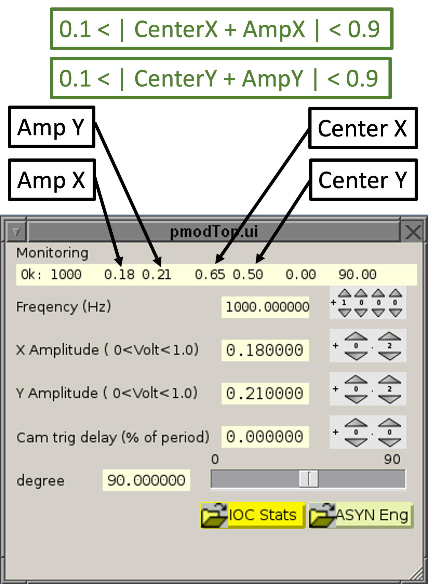
The modulator has two axis (see figure below). Each axis has two parameters, center and amplitude. Every time that an offset is applied, the modulator center changes. The amplitude is set automatically during the acquisition.
Recentering the modulator requires the intervention of the observing assitant or staff astronomer and should be done between QACITS sequences.
Please, ask your SA or OA to recenter the modulator following this procedure:
prtcQuickAccess.pyOpen the Misc tab, and click on Center modulator.
mov command to move the star close to the
vortex.
The procedure described above can be used any time during the observations, including the acquisition, calibration sequence or optimization sequence, if the modulator reaches a limit.
If a QACITS sequence fails, but you still want to observe the same target, it is very likely that one of the AO stages has ended in a position that is not aligned with the telescope anymore. This may lead to incosistent offsets if further attempts are made to recenter the star on the vortex in order to start a new QACITS sequence. The recommendation in this case is to reacquire the target from scratch. This is particularly important for observations with the PyWFS, because some of the offsets rely on the pyramid modulator, which has a very small range (~1"). The modulator can easily be sent out of range, if a failed QACITS sequence commands a bad offset.
If you need to interrupt a QACITS sequence, the way to proceed is to issue a Ctrl-C on the IDL terminal where QACITS is running. Make sure to answer n when asked if you would like to interrupt the current exposure, otherwise the the NIRC2 detector keyword server (alad) may die and it will need to be restarted. Then wait for the current exposure to be completed. Once the exposure is completed, the IDL prompt should be available again. If it is not, please, try Ctrl-C again. Once the QACITS sequence stops, look at the latest offsets on FACSUM. If the offsets are larger than ~0.3", you may need to recenter the star on the vortex before launching a new QACITS sequence.
Sky flats are more appropriate for observations taken in the Lp and Ms filters. Dome flats can be taken for observations in the Ks and Kp filters, since the integration times to provide a high enough sky background tend to be long.
	      object flat
	      subc [same value as used for the science observations]
	      sampmode 2
	      tint [0.5 for Lp and 0.25 or 0.3 for Ms]
	      coadd 1
	      corona clear
	      wait4ao off
and take a test image:
itest
	      coadd 10
	      goi 10
Take a sequence of 10 darks for each combination of subc, tint, sampmode and coadd
On a vm-nirc2 terminal:`
      object dark
      shutter closed
      subc [match value for science and flat frames]
      tint [match value for science and flat frames]
      sampmode [match value for science and flat frames]
      coadd [match value for science and flat frames]
      goi 10
Once the darks are completed shut down the NIRC2 software following the end-of-night instructions.
Spectroscopy is rather more complicated with NIRC2 than with other instruments. NIRC2 uses grisms for high throughput, but does not include a means of tilting the grisms to change the wavelength range accessible on the detector. Instead, the spectrum is shifted by moving the slit and science target within the AO system's focal plane. In fact in some situations you may not be able to image the target through the slit with the camera you want to use for the spectra. You may have to use a camera with a wider field of view, or trust in a blind offset in order to center the target in the slit. Below we outline the steps and commands suggested in order to setup for spectroscopy.
Below we outline the steps involved in planning the spectroscopy, and setting up on the target and taking the spectra.
Currently the broadband filters J, H, K, Kp, Lp, and Ms are appropriate for spectroscopy. Spectroscopy with the Lp and Ms filters requires the slit to be well off center, to the extent that the only way to image the slit is with the wide camera. Ms is very narrow, and it remains to be seen how useful it will prove for spectroscopists.
Once you have chosen a band, you can use the "slitcol" command to calculate the required slit position. Just type the command and it will prompt you for the grism, camera, central wavelength, and order. (It will choose an order, which will generally be the appropriate one for your central wavelength). For example, if you want to get the entire Kp bandpass on the wide camera with the medium resolution grism, you would respond to slitcol with the appropriate information, using 2.124 as the central wavelentgth (the central wavelength of the Kp filter).
The slitcol command will print the expected slit column numbers for all three cameras for that particular central wavelength. It will also load four important parameters. By far the most important parameters is SLITMM, which is the camera-independent slit position (in millimeters from some relatively arbitrary zero point) in the AO focal plane. Once you get a setup you like, you should record the SLITMM value.
Also, we suggest you write down the relevant column numbers for all three cameras, or at least the narrow camera in addition to the camera you will use for spectroscopy. The reasoning behind the latter suggestion is that you may want to line up the target in the slit using the narrow camera, where you can see the object better.
Two other parameters saved are the camera requested (in CAMNEXT) and the grism requested (in GRSNEXT). These are only used by the "spec" command (see below), which you may not use in any case. The last parameter saved is SLITCOL, the expected column of the slit for the requested camera. You probably want to record this value as well (in fact, it might not hurt to record all three column numbers for all three cameras). This value is only used for your initial setup information, so it does not need to be set, although it is displayed on the NIRC2 Status Display.
You may want to know either (a) how much spectrum will you get on the detector, or (b) how much room you have to adjust the slit left or right.You may want to adjust the slit left or right in order to make sure that the guide star lies within the range available to the FSM (field steering mirrors). This can be gleaned from Tables 2.2 (lowres grism) and 2.3 (medres grism).
In order to tweak the slit position, you will need to change SLITMM. One way of doing this is to rerun slitcol with a slightly different central wavelength, repeating this until you converge on the appropriate column value. Record the value of SLITMM at this point. Or you can run slitcol at two wavelengths, calculate the change in SLITMM per micron, and then calculate the new value of SLITMM.
In some situations it is possible to select a value of SLITMM that will allow you to get whole spectra in multiple filters. In general this is only possible for J(5), H, and K or Kp filters. [J(5) represents the fifth order J spectrum.] In particular:
Table 5.4 Slit settings useful for multiband spectroscopy.
| Grism |
Camera
|
SLITMM
|
SLITCOL
|
coverage
|
|
| lowres |
wide
|
-1.1
|
484.43 (wide)
454.12 (medium) 383.36 (narrow) |
J(5), H, K, Kp
|
|
| medres |
wide
|
3.9
|
656.95 (wide)
799.47 (medium) 1076.29 (narrow) |
H, K, Kp
|
When you select a value of SLITMM like this, you can read the SLITCOL value from the table above. However, in other circumstances you will not immediately know how at what column the slit will be seen. Unfortunately we have only a rudimentary way of determining this. You can run the "slitcol" command and change the requested central wavelength until you get the correct SLITMM value. Then read the SLITCOL values for the appropriate camera from the slitcol output. (Note that the slitcol command can accept all of its parameters on the command line, making it easier to "up-arrow" and change central wavelengths.)
What you will end up with for each of your spectroscopy setups, is a value of SLITMM, the camera you will use, the filter you will use, and the grism you will use.
Once you have afternoon access to the instrument, you can check the slit column values for your various spectroscopy setups. Change to the desired camera and grism, and set the SLITMM value using the "slitmm" command. Once the camera has been commanded into position and SLITMM has been defined, you can insert the slit using the "slit" command. (This command will look at the destination of the camera slide if it is in motion, so you do not need to wait until the camera actually arrives there.)
With everything in place, take an image of the slit. You can calculate a width using the Gaussian Fit tool on Quicklook (under "Plot"). Place the cursor on the slit image near the desired row number (usually row 512 by default) and click the button. The Y FWHM and center may be completely ridiculous, but the X FWHM and center should still be good. (Make sure the X FWHM value is reasonable and corresponds roughly to the expected slit width in pixels.) This will give you an updated, better estimate of the slit column.
You should record these measured slit column values. They will be needed when you center the target on the slit.
This procedure of refining the slit column can either be done in the afternoon or once you are on sky.
Next, image your target with whatever camera you need to see the slit. Center it using the mov x1 y1 x2 y2 command. This command takes the observed (x,y) coordinates as the first input pair, and the destination (slit) (x,y) coordinates as the second pair. It then sends the appropriate telescope moves to put the object on the expected slit position.
You can take another image at this point to confirm that the target has moved to the expected (x,y) coordinates (as printed by the original slitcol command).
Insert the desired slit, "x", using this command. It will read the current value of SLITMM and position the slit and slit mask appropriately.
Take an image through the slit to confirm that it looks well centered. It can be tweaked into position better using the "X x" (which moves in arcsec) or "px x" command (which moves in pixels).
You can either type "spec [filt]", with an optional filter name, or simply insert the grism and camera using the "grism" and "camera" commands. Often you will not be changing the filter or camera from the images you used to align to the slit. In thijs case the "grism" command is all you will need.
Inserts the grism requested in the original "slitcol" command, and (optionally) a filter. The filter would be used for order blocking. If no filter is specified a default will be used. Note that the spec command will insert a grism independent of its location: filter wheel or grism slide.
Note that in some circumstances, in particular when doing Lp or Ms spectroscopy, you may well be centering your target using a different camera and filter combination. In thjis case, as long as CAMNEXT and GRSNEXT are set appropriately, it may be easier to use "spec lp" or "spec ms" to change all three settings (camera, grism, and filter) at once.
Typically observers will want to use one of the spectroscopic dither patterns. You may also want to use the sltmov dy [dx] command to move along the slit and create your own dither pattern.
Table 5.5 Slit Dither Patterns
| sltmov dy [dx] | Move the telescope parallel to the slit by dy arcsec, and perpendicular to the slit by dx arcsec. With this command you can create your own dither patterns. |
| sp2 dy [n] | Dither along the slit in two positions separated by dy arcsec. An optional parameter allows you to repeat the pattern n times. |
| sp3dy [n] | Dither along the slit in three positions separated by dy arcsec. An optional parameter allows you to repeat the pattern n times. |
| sp5 dy [n] | Dither along the slit in five positions separated by dy arcsec. An optional parameter allows you to repeat the pattern n times. |
| sp7 dy [n] | Dither along the slit in seven positions separated by dy arcsec. An optional parameter allows you to repeat the pattern n times. |
AO observers often are interested in the spatial resolution of a target,
including in spectroscopy mode. If you have the desire to scan a slit across
a resolved target and get spectra at different spatial positions, there are
two ways to accomplish this. The first way is the usual method of moving the
telescope a slight amount perpendicular to the slit. You can use the "sltmov"
command with the second parameter. For example "sltmov
0 0.08" will move the telescope 80 milliarcsec perpendicular
to the slit (the object will move to the left, for a positive dx).
Unfortunately, this technique carries a significant overhead with it in unlocking
the AO, offsetting the telescope, moving the AO Field Steering Mirrors, waiting
for things to settle into position, then relocking on the guide star. A more
efficient technique may suffice for some uses.
In the second technique, rather than move the telescope we move the slit itself. This has two big advantages: (1) it does not carry with it the overhead that offsetting the telescope does, and (2) it is significantly more precise. (The mechanism that carries the slit will position to within a micron, 0.7 milliarcsec, or better!) It also has a disadvantage: the changing wavelength scale and the resulting complication in data reduction. Before we discuss details about this second technique, let's describe how it would work.
The movslit command accepts an argument giving it the number of columns (in the current camera) to move the slit. Hence "movslit 4" will move the slit four columns to the right (higher column numbers) in the current camera. Typically you would set up either on the edge of your target or just off it, then issue a series of "movslit dX ; goi" commands to take data at different positions across the object. Alternatively you might want to start at the center and move the slit across in one direction, then back from the center towards the other direction or even alternate "left-right, left-right."
Issues:
There are a number of issues, some of which may not be of great concern, but others which might be showstoppers for this movslit technique.
Imaging in the thermal infrared differs somewhat from 1-2.5 µm imaging. This section will be fleshed out as we get more experience in thermal IR imaging during commissioning. Working in the thermal infrared with broad passbands, it is easy to saturate the detector with even the shortest exposure times in full-frame mode. You can decrease the rate at which the pixels saturate by choosing a filter with a narrower bandpass, or a camera with a finer scale. CDS mode will saturate before single-sample readout mode (sampmode 1). By using subarrays of the full detector, you can access shorter integration times than with the full detector. Other possible techniques may include increasing the pixel sampling rate, using a different pupil mask, and moving the preslits to block some of the incoming light
To decrease your readout overhead, you may also want to use a large number of coadds. Each coadd has essentially no overhead, wherease reading a frame carries a significant penalty in time. Note, however, that a frame of 100 coadds is not exactly the same as the sum of 100 frames of 1 coadd each
The following lists minimum exposure times estimated from reasonable telescope and AO parameters and some more or less well-known NIRC-2 parameters. The table will eventually be updated once thermal IR commissioning is done on Maunakea.
To use the table, typically you would select the bandpass and camera you want, and read off the minimum integration time. Then, from Table 5.7 you would find a subarray that provides this integration time or a lower one.
Table 5.6 Minimum integration times
|
Filter
|
Photon
rate (photons/sec/pixel) |
T(min)
(seconds) |
||||
|
narrow
|
medium
|
wide
|
narrow
|
medium
|
wide
|
|
|
Ls
|
30,000
|
120,000
|
480,000
|
6.7
|
1.7
|
0.42
|
|
L
|
220,000
|
880,000
|
3,500,000
|
0.90
|
0.23
|
0.057
|
|
L'
|
190,000
|
760,000
|
3,100,000
|
1.04
|
0.26
|
0.065
|
|
Ms
|
760,000
|
3,000,000
|
12,000,000
|
0.26
|
0.066
|
0.016
|
|
M
|
1,500,000
|
6,000,000
|
24,000,000
|
0.13
|
0.033
|
0.008
|
Note that the effective integration times shown above are the same for single-sample mode (sampmode 1) and CDS mode (sampmode 2). In spite of this, however, CDS mode images will saturate before single-sample mode images. This probably sounds counterintuitive, so an explanation is worthwhile.
In single-sample mode, the detector is reset, pixel-by-pixel. It takes T(min) seconds to do the whole array. Then the array starts reading out the detector. It has been T(min) seconds since the first pixel has been reset, so it has been integrating for T(min) seconds. A little thought shows this is true for all of the pixels.
In CDS mode, the array is reset. Then the first, nondestructive read is performed. The pixel has already been integrating for T(min) seconds. After this first read the second read is started. Now a given pixel has been integrating for 2*T(min). The two reads are subtracted, leaving an effective integration time of T(min) seconds, but clearly the second read in CDS mode can saturate at half the photon rate of single-sample mode, distorting the resulting subtraction.
However, single-sample mode may be more difficult to reduce and analyze. If you do not need a large field of view, you may consider using a subarray with half the number of pixels but read out in CDS mode.
By reading out only a subsection of the detector, the minimum integration time is decreased, as low as 0.0025 sec. The readout software supports only a limited range of subarrays, constrained by three rules:
- The size in X must be divisible by 32,
- The size in Y must be divisible by 8, and
- The product Nx * (Ny+8) must be divisible by 4096
This allows for 770 different subarray shapes. A full table of allowable subarray sizes and minimum integration times is provided elsewhere. To make life simpler here we recommend a set of subarrays with a range in minimum integration times. These are squarish arrays. You may want long, short subarrays for spectroscopy, although with the dispersing power of the grism you should be able to get away with longer exposure times. Spectroscopic subarrays are not currently covered, as it is highly uncertain what the limiting fluxes will be for the various grism, central wavelength, and camera combinations. Below is a list of recommended imaging arrays. Note some interesting trends; often the narrow-field camera provides mor esquare arcseconds of sky coverage than the medium- or wide-field cameras. This is because the smaller (in arcsec) pixels of the narrow camera allow a larger subarray window.
The command for issuing subarrays which autmatically finds the nearest legal dimension is:
subc [xdimension] [ydimension]
Table 5.7 Recommended imaging subarrays
|
Nx
|
Ny
|
T(min) (ms) |
Narrow FOV
(arcsec) |
|
1024
|
1024
|
181
|
10.2x10.2
|
| 768 | 776 | 109 | 7.7 x 7.7 |
|
512
|
512
|
52.8
|
5.1 x 5.1
|
256
|
264
|
17.6
|
2.5 x 2.6
|
|
128
|
152
|
7.5
|
1.3 x 1.5
|
|
64
|
56
|
2.6
|
0.6 x 0.6
|
The telescope's adaptive optics (AO) system will generally be run by the Observing Assistant (OA) or AO Support Astronomer (AOSA). There are a number of features of the NIRC2 environment, however, that allow the observer to control the instrument/AO interaction. Foremost among these is control over whether the AO system tries to lock on a star or not. The AO actually has a number of flags to tell when various parts of the system are ready. While observing you will generally want exposures to make sure that both the tip-tilt (TT) and the deformable-mirror (DM) loops are closed. However, when you are taking calibration frames, either in the afternoon before observing, or during the night, you will not expect to wait for any loops to close.
At night you may want to offset to sky and take a sky image without locking the AO system. Using the nod, tosky, and fromsky commands facilitate this. The tosky command records the state of AO locks, and turns them off. This allows for arbitrarily large nods to sky without worrying about exceeding the range of the FSMs (field steering mirrors). Using fromsky then resets the lock states to the saved values.
Most of this interaction is controlled via the ``wait4ao'' command. In the afternoon the waits are turned off using ``wait4ao off''. This should be the state when you initialize the instrument after logging on. (As with many commands, if you just type ``wait4ao'' without arguments, the current state will be shown.) When observing starts you will want to type ``wait4ao on'' to turn on the wait for the AO locks.
Note that you can fine tune this somewhat, with the wait4tt, wait4dar, and wait4dm commands. wait4tt turns on or off the flag that waits for the tip-tilt loop to lock, wait4dar turns on or off the offloading for the DAR (Diffrerential Atmospheric Refraction) compensation, and wait4dm turns on or off the flag that waits for the deformable mirror to lock. If you only want to use tip-tilt, for example, you would type ``wait4dm off'' to turn off the DM wait.
The DAR (differential atmospheric refraction) correction deserves some description. This corrects for the differential atmospheric refraction between the optical-wavelength wavefront sensor and the infrared science detector. It is necessary to keep the target well centered during long exposures, in particular for spectroscopy. There are two forms of the correction. Whenever a telescope move is requested (slew to a new target, or dither on the same target), the total DAR correction is calculated and sent to the FSMs. Once AO is locked, however, the FSMs cannot be moved (they are too coarse and have backlash), so the correction can be made by changing the tip-tilt offset (AO keyword DTCLOF). It is not good to have this tipt-tilt offset grow too large, as AO performance will start to suffer, so during long stare observations (without any dithering) you may want to pause and send a move to the FSMs to offload the tip-tilt offset. It is expected that this will be a very rare occurrence, however.
The observer is also provided with an AO status and control screen, that provides feedback on the overall state of the AO system.
At times in the past the observatories on Mauna Kea have been asked not to FTP data to the home institutions of the observers. This was because all of the observatories shared a relatively low band width connection to Oahu. Currently the connection is large enough to handle most observers' data, including NIRC2 files. So feel free to FTP data home.
You may also use scp, although it is generally more problematic than FTP.
From Waimea what often works is
scp local_file remote_user@host:remote_file
Log files are located on the instrument machine. Type "cdlog" to go to the log directory. Normally log files are not used by observers, but may be used by instrument support in order to track down problems. Since they are generally used locally to Keck, they tend to grow to rather large sizes, which may make it inconvenient for observers to extract only the parts relevant to their run. We request that if you wish to reduce the size of the log file, copy it to a scratch disk (see section 6.1.2) and edit it first.
The log files include:
Table 6.1 Log files
| Filename | Description |
| AladInstr.log | A dump of alad keywords every 5 minutes. |
| ControlLog | Input and output from an xterm designated as the "Control Window" for NIRC2. Note that NIRC2 commands can be typed from any window, but only the designated window will get logged to this file. |
| nirc2info | A log of motor daemon keyword changes. |
| nirc2log | A log of keyword changes and alad server output. This list is shorter than that in nirc2info, but includes the most important ones. It is also the file generally used by the "tklogger" alarm handler. |
| server.log | Alad server output. |
| startup.log | A log file that will eventually contain the output from the startup procedure. |
| swap.log | A log of swap space available. |
The following tables have been taken partly from the original NIRC2 proposal by Keith Matthews and Tom Soifer, and partly from more recent information on the as-built instrument.
Table 7.1 General Specifications
| Input f/ ratio | f/15 |
| Wavelength range | 0.9-5.3 microns |
| Field of view | 10x10 arcsec 20x20 arcsec 40x40 arcsec |
| Pixel scale |
0.01 arcsec/pixel |
| Filters | Z, J, H, K, Ks, Kp, L, Ms, H2, Fe II |
| Pupil mask | two circular fixed, four hexagonal, rotating |
| Slits | 10, 20, 30, 40, 60, 80, 120, and 160 milliarcsec |
| Coronagraphic spots | circular: 100, 150, 200, 300, 400, 600, 800, 1000, 1500, 2000 milliarcsec |
| Grisms | medres and lowres grisms (see table 5.4), pupil imaging lens, and clear (imaging mode). Type 'help grism' for more information |
| Minimum frame time | 0.182 sec, full frame |
| Detector | 1024x1024 InSb Aladdin-3 array, 27 micron pixels 32 simultaneous outputs, grouped in 8 pixels across a row in each of 4 quadrants gain ~4 electrons/DN subarray capability 35 K operating temperature |
| Read noise | 38 electrons/read 11.5 DN/sqrt(N) for N samples in MCDS mode, up to N = 64, dropping more slowly beyond that until at least N = 512. (Note that N = 2 corresponds to two reads, or CDS mode.) |
| Dark current | < 0.1 electrons/pixel/sec |
| QE | 80% at 1.7 microns |
| Well depth |
40,000 electrons (10,000 DN) linearity limit 72,000 electrons (18,000 DN) 5% linear |
NIRC2 estimated sensitivity: see Table 2.1.
The following table shows the filters in each position of the two filter wheels. Note that the ``filt" command usually specifies both wheel positions, choosing either an open position or an appropriate blocking filter along with the primary filter. The ``F" numbers shown in the table are unique serial numbers which specify the exact piece of glass.
Table 7.2 Filter Positions
|
Filter Wheel 1
|
Filter Wheel 2
|
|||||
|
Position
|
Filter
|
F number
|
Position
|
Filter
|
F number
|
|
|
1
|
J
|
F499
|
1
|
Bra_cont
|
F544
|
|
|
2
|
H
|
F501
|
2
|
Jcont
|
F534
|
|
|
3
|
CH4_short
|
F536
|
3
|
PaBeta
|
F533
|
|
|
4
|
CH4_long
|
F539
|
4
|
Hcont
|
F514
|
|
|
5
|
Y
|
F559
|
5
|
FeII
|
F513
|
|
|
6
|
Ks
|
F503
|
6
|
He1_B
|
F538
|
|
|
7
|
Kp
|
F505
|
7
|
H2_1-0
|
F517
|
|
|
8
|
PaGamma
|
F547
|
8
|
Br_gamma
|
F511
|
|
|
9
|
K
|
F506
|
9
|
H2_2-1
|
F527
|
|
|
10
|
z
|
F541
|
10
|
Kcont
|
F512
|
|
|
11
|
H2O_ice
|
F537
|
11
|
CO_2-0_bh
|
F528
|
|
|
12
|
PK50_1.5
|
F496
|
12
|
PAH
|
F535
|
|
|
13
|
18hole_msk
|
—
|
13
|
9holeMsk
|
—
|
|
|
14
|
Lw
|
F556
|
14
|
Wollaston
|
F560
|
|
|
15
|
Lp
|
F508
|
15
|
PK50_1.5
|
F495
|
|
|
16
|
Ms
|
F509
|
16
|
PK50_1.0
|
F492
|
|
|
17
|
clear
|
—
|
17
|
clear
|
—
|
|
|
18
|
He1_a
|
F540
|
18
|
Br_alpha
|
F545
|
|
Command examples:
slit 10
slit 120
Table 7.3 Slits
| slit10 slit20 slit30 slit40 |
slit60 |
Command examples:
corona 300
corona 1000
Table 7.4 Regular Coronagraphic Spots
| corona100 corona150 corona200 corona300 corona400 |
corona600 corona800 corona1000 corona1500 corona2000 |
Command examples:
vcorona vortexk
vcorona vortexlm
Table 7.5 Vortex Coronagraphic Spots
| vortexk |
| vortexlm |
The following is an alphabetical list of NIRC2 commands. Almost every command is covered, including low-level commands that are generally never called directly by observers. The rightmost column indicates the command "class":
D = detector
d = display
E = engineering (not generally used by observers)
H= information
I = imaging
M = motors
Table 7.5 Full Command List
There are three separate keyword libraries for NIRC2: alad (for the detector), nirc2 (for the motors), and pmr (for the pupil rotator). NIRC2 often commonly talks to three other keyword libraries: AO, DCS, and ACS. Most keywords can be shown using "show -s service keyword" and changed using "modify -s service keyword". In these commands "service" is "alad" for the Aladdin keywords, and "nirc2" for the motor keywords.
Examples:
show -s alad coadds (shows the current number of coadds set) modify -s nirc2 camname = wide (inserts the wide-field camera into the beam)
A Web page on photometric standards such as the HST/NICMOS standards, Elias standards, and UKIRT faint standards is available.
There are four emission line lamps available for wavelength calibration of spectra: Ne, Ar, Kr, and Xe. Sample calibration spectra are available.
Also useful for wavelength calibration are the night sky emission lines.
There may have been some IDL problem. You can open the IDL text window (which
normally will be iconified) and see if there is some evidence for a crash.
To recover, select "NIRC2 Tools → Subcomponents → Restart QuickLook"
or type "nirc2 restart quicklook"
on a command line.
Are you using single-sample mode, and does your image look like this:
\
This is probably a display artifact. Zoom in by clicking the "Z+" button and see if the banding goes away. In single-sample mode you can see an odd-even effect in the rows of the image. Odd rows are either systematically higher or lower than the even rows. The problem here is that with some combinations of image size and display size you will see a beating pattern between the odd-even pattern and the algorithm that QuickLook uses to decide which pixels to display in its window. For a number of rows it may choose every odd numbered row, then switch to every even-numbered row for awhile, then back to odd, etc. Note that CDS or MCDS images won't display this effect.
The script "check tasks," (only works on waikoko) will list a variety of NIRC2 tasks running on waikoko. A typical output is shown below:
waikoko{nirc7}: ct
nirc5    29324 12:22:01  0:01 NIRC2 Command Window -geometry 80x20+10+10 -
nirc5    29326 12:22:01  0:00 NIRC2 Log File -e tail -f /sdata800/logs/nir
nirc5    29354 12:22:03  0:00 NIRC2_Status_Display
nirc5    29401 12:22:04  0:00 NIRC2_Status_Display
nirc5    29323 12:22:01  0:00 NIRC2_Temp_Display  -geometry 244x400 -t
nirc5    29347 12:22:03  0:00 NIRC2_Temp_Display  -geometry 244x400 -t
nirc2eng 14514   Mar 01  0:00 alad_server_bin -noacs
nirc2eng 14515   Mar 01  0:00 alad_server_bin -noacs
nirc2eng 14516   Mar 01  1:20 alad_server_bin -noacs
nirc2eng 16722   Mar 02  0:00 caRepeater
nirc5    29313 12:21:59  0:00 dcsSim dcs2sim
nirc5    29499 12:22:05  6:15 idl rstartup
nirc5    14271   Mar 01  0:01 nirc2_io_daemon
nirc2eng 14295   Mar 01  0:14 nirc2_mtr_daemon
nirc5    29230 12:21:56  0:06 tklogger -f /home/nirc2/bin/tklo
The enhanced "check tasks" script only works on vm-nirc2. It provides a complete list of tasks that need to be running on different computers during night operations.
There are two ways to run the ctx script:
The following is typical ctx output when all NIRC2 software is running during night operations:
nirc2{nirc3}21: ctx
Host      Process             Type     Want  Got Status
----      -------             ----     ----  --- ------
nirc2     nirc2mon            daemon    1     1  OK
nirc2     nirc2noc2           daemon    1     1  OK
nirc2     nirc2plus           daemon    1     1  OK
nirc2     nirc2soundboard     daemon    1     1  OK
nirc2     eventsounds         inst      1     1  OK
nirc2     pig_main            inst      1     2  OK
moolelo   nirc2history        daemon    1     1  OK
waikoko   fileMover           daemon    1     1  OK
waikoko   alad_server_bin     daemon    3     3  OK
waikoko   caRepeater          daemon    1     1  OK
waikoko   io_daemon           daemon    1     1  OK
waikoko   mtr_daemon          daemon    1     1  OK
waikoko   nirc2_log           inst      1     1  OK
waikoko   status_display      inst      2     2  OK
waikoko   watch_keywords      inst      1     2  OK
waikoko   quicklook           inst      2     2  OK

Current WAIKOKO tasks:
nirc2eng   401        0.1   0.1 0.1        560        ?        S     Dec_17    01:00:17 fileMover
nirc2eng   13907      0.5   1.5 1.5        30512      ?        S     Jan_03    8:24     alad_server_bin
nirc2eng   13906      0.0   0.1 0.1        1240       ?        S     Jan_03    0:00     alad_server_bin
nirc2eng   13905      0.0   0.1 0.1        984        ?        S     Jan_03    0:00     alad_server_bin
nirc2eng   13904      0.0   0.1 0.1        1304       ?        S     Jan_03    0:04     caRepeater
nirc2eng   1918       0.0   0.1 0.1        1296       pts/0    S     Dec_17    0:20     io_daemon
nirc2eng   1950       0.1   0.1 0.1        1168       pts/0    S     Dec_17    8:24     mtr_daemon
nirc3      8646       0.0   0.2 0.2        3624       pts/2    S     00:18:15  0:00     nirc2_log
nirc3      8665       0.1   0.8 0.8        15056      pts/2    S     00:18:16  0:00     status_display
nirc3      8818       0.0   0.1 0.1        1464       pts/2    S     00:18:20  0:00     status_display
nirc3      8517       0.1   0.7 0.7        13456      pts/2    S     00:17:59  0:00     watch_keywords
nirc3      8519       0.0   0.1 0.1        1136       pts/2    S     00:18:00  0:00     watch_keywords
nirc3      8660       0.1   0.2 0.2        2976       pts/2    S     00:18:15  0:00     quicklook
nirc3      8664       3.9   1.1 1.1        21600      pts/4    S     00:18:16  0:04     quicklook

Current VM-NIRC2 tasks:
nirc2run   20593      2.0   0.5 85308      21872      ?        Sl    2021      337:00   nirc2mon
nirc2run   19615      0.0   0.0 123728     1816       ?        S     2021      170:03   nirc2noc2
nirc2run   8289       0.2   0.3 850636     12624      ?        Sl    Jan03     4:03     nirc2plus
nirc2run   20070      0.0   0.1 42904      6940       ?        Sl    2021      1:05     nirc2soundboard
nirc3      22583      0.4   0.4 215980     19212      ?        Sl    00:17     0:00     eventsounds
nirc3      23365      0.1   0.1 167944     7064       ?        S     00:18     0:00     pig_main
nirc3      23368      2.5   2.0 1204280    79080      pts/58   Ssl+  00:18     0:00     pig_main

Current MOOLELO tasks:
nirc2run   144527     0.9   0.0 56268      11284      ?        Sl    Jan03     16:55    nirc2history

Daemon status:      OK
Instrument status:  OK
Both, the Daemon status and Instrument status should be OK when all the NIRC2 software is running normally.
The testAll checks the following:
There are two ways to run the testAll script:
The following is example of a successful run of testAll when all NIRC2 software is running and NIRC2 is the selected instrument:
nirc2{nirc3}: testAll
Checking NIRC2 computers:
  Checking moolelo.................OK       (Keyword history)
  Checking nirc2...................OK       (Linux virtual host)
  Checking waikoko.................OK       (Instrument target host)
Checking waikoko daemons:
  Checking alad_server_bin.........OK
  Checking caRepeater..............OK
  Checking fileMover...............OK
  Checking nirc2_io_daemon.........OK
  Checking nirc2_mtr_daemon........OK
Checking vm-nirc2 daemons:
  Checking nirc2mon................OK
  Checking nirc2noc2...............OK
  Checking nirc2plus...............OK
  Checking nirc2soundboard.........OK
Checking moolelo daemons:
  Checking nirc2history............OK
Checking NIRC2 applications:
  Checking NIRC2 Log File..........OK
  Checking NIRC2_Status_Display....OK
  Checking pig_main................OK
  Checking rnirc2startup...........OK
  Checking tklogger................OK
  Checking watch_keywords..........OK
Checking NIRC2 keyword libraries:
  Checking ACS.....................OK
  Checking Alad server.............OK
  Checking Camera..................OK
  Checking Cold head 1.............OK
  Checking Cold head 2.............OK
  Checking DCS.....................OK
  Checking Grism...................OK
  Checking Inner filter wheel......OK
  Checking Inner pre-slit slider...OK
  Checking Outer filter wheel......OK
  Checking Outer pre-slit slider...OK
  Checking Pupil mask rotator......OK
  Checking Pupil mask stage........OK
  Checking Shutter.................OK
  Checking Slit mask slider........OK
  Checking Slit slider.............OK
  Checking Temperature readings....OK
  Checking Temperature settings....OK
  Checking nirc2history............OK
  Checking nirc2plus...............OK
Checking NIRC2 settings:
  Checking Bench temperature......................................OK
  Checking Camera temperature.....................................OK
  Checking Collimator temperature.................................OK
  Checking Current instrument.....................................OK
  Checking Detector block heater output...........................OK
  Checking Detector block temperature.............................OK
  Checking Detector temperature...................................OK
  Checking Detetector temperature set point.......................OK
  Checking Getter temperature.....................................OK
  Checking Rotator CCW limit......................................OK
  Checking Rotator CW limit.......................................OK
  Checking Shield temperature.....................................OK
  Checking Single-stage coldhead power............................OK
  Checking Single-stage coldhead speed readback...................OK
  Checking Single-stage coldhead speed set point..................OK
  Checking Single-stage coldhead temperature......................OK
  Checking Two-stage coldhead high-stage temperature..............OK
  Checking Two-stage coldhead high-stage temperature set point....OK
  Checking Two-stage coldhead low-stage temperature...............OK
  Checking Two-stage coldhead power...............................OK
  Checking Two-stage coldhead speed readback......................OK
  Checking Two-stage coldhead speed set point.....................OK
  Checking Two-stage colhead high-stage heater output.............OK
-------------------------------------
 0 errors and  0 warnings were issued
-------------------------------------
There should be 0 errors and 0 warnings when all the NIRC2 software is running normally at night, and NIRC2 is the selected instrument on the telescope control system.
The "recover" script is used to recover from an alad server crash. The consequences of an alad server crash have increased since November 2021, because there are more NIRC2 services that depend on a healthy detector server than in the past. Unfortunately, the alad server is not designed to enable automatic reconnection from other daemons and applications when it dies. Therefore, when there is an alad server crash, several applications and daemons need to be shut down before the alad server is restarted. The applications and daemons should be restarted once the alad server is running again.
Since January 1, 2022, there is new version of the recover script, only available on vm-nirc2, that supersedes the old recover script on waikoko. This new version of recover handles the shutdown and restart of all the software that depens on the alad server, in addition to restarting the alad server tasks.
The recovery sequence consists of the following steps:
There are two ways to run the recover script:
The new recover script can be run as any of the NIRC2 numbered accounts (nirc1, nirc3 to nirc9), and as nirc2eng on vm-nirc2. If the script is run as nirc2eng, it will kill all running instances of the quicklook, status display and PIG. If it is run as one of the NIRC2 numbered accounts, it will only kill the running instances of quicklook, status display and PIG owned by that account.
The following shows a successful recover output:
nirc2{nirc3}: recover

#-------------------------------#
# Starting alad recovery script #
#-------------------------------#

/kroot/rel/default/bin/recover will kill any exposure in progress.
Do you wish to continue (y/n) [n]? y

- Searching quicklook processes...
Quicklook pid 10597 is owned by nirc2eng. Cannot be killed by user nirc3.
Quicklook pid 10598 is owned by nirc2eng. Cannot be killed by user nirc3.
Killing quicklook pid 11450 owned by nirc3...
Quicklook pid 11454 owned by nirc3 has already been killed. Nothing to kill.

- Searching status display processes...
Status display pid 10744 is owned by nirc2eng. Cannot be killed by user nirc3.
Status display pid 10745 is owned by nirc2eng. Cannot be killed by user nirc3.
Killing status display pid 11455 owned by nirc3...
Status display pid 11611 owned by nirc3 has already been killed. Nothing to kill.

- Searching Program Identification GUI (PIG) processes...
Killing PIG pid 2663 owned by nirc3...
PIG pid 2666 owned by nirc3 has already been killed. Nothing to kill.

- Stopping nirc2plus service...
nirc2plus       : Sending SIGTERM to pid:  30956

- Stopping nirc2history service...
nirc2history    : Sending SIGTERM to pid:  60267

- Restarting alad server...
Copying ./sdata900/logs/alad.cfg to /sdata900/logs/alad.cfg.save...

Hunting alad_server_bin processes on waikoko...
nirc2eng 3886 -noacs
Kill -9 sent to pid = 3886.
nirc2eng 3884 -noacs
Kill -9 sent to pid = 3884.
nirc2eng 3885 -noacs
Kill -9 sent to pid = 3885.

Hunting mystery processes on waikoko...

nirc2eng 3880 logger
/tmp/TEMPFITS: No such file or directory
/tmp/FRAME: No such file or directory
/scratch/buf4.fits: No such file or directory

Hunting caRepeat processes on waikoko...
nirc2eng 3883 caRepeater
Kill -9 sent to pid = 3883.
Checking for existing servers (real and simulated)...
Testing transputer communication, try 1 of 3...
Transputer communication OK.
Running server program.
[1] 13900 13901

Sleeping for 5 seconds...

Checking number of alad_server_bin processes...
Found 3 instances of alad_server_bin. Need 3.

- Restoring NIRC2 alad keyword data from /sdata900/logs/alad.cfg.save on 2022-01-03 16:53:26.0...


- Calling scripts to modify keyword values...
setting observer = Eng1,Eng2 (wait)
setting object = Test1 (wait)
setting outdir = /sdata904/nirc3/2022jan04/ (wait)
setting frameno = 1 (wait)
setting itime = 1.000 (wait)
setting coadds = 1 (wait)
setting sampmode = 2 (wait)
setting x_extent = 1024 (wait)
setting y_extent = 1024 (wait)

- Restored alad keywords...
                      observer = Eng1,Eng2
                        object = Test1
                        outdir = /sdata904/nirc3/2022jan04/
                       frameno = 1
                         itime = 1.000000 seconds
                        coadds = 1
                      sampmode = 2
                      samprate = 200
                     multisamp = 2
                      x_extent = 1024 pixels
                      y_extent = 1024 pixels


- Starting nirc2history service...
Starting nirc2history (/kroot/rel/default/bin/keygrabber  -c /kroot/rel/default/data/nirc2/keygrabber.conf)

- Starting nirc2plus service...
Starting nirc2plus (/kroot/rel/default/sbin/nirc2plusd  -c /kroot/rel/default/data/nirc2plus/nirc2plus.conf)

- Starting PIG as nirc3 on display nirc2:7...
[1] 8306

- Starting status display as nirc3 on display nirc2:6...
[2] 8322
[2]  - Done                          kixrsh waikoko nirc2 start statusd

- Starting quicklook as nirc3 on display nirc2:6...
[2] 8378
[2]  - Done                          kixrsh waikoko nirc2 start quicklook
- Arranging NIRC2 GUIs...

#--------------------------------#
# Alad recovery script completed #
#--------------------------------#