IMPORTANT NOTES:
-
As of April 2024, we encourage DEIMOS observers to use the new
Python-based Slitmask Design Tool
(SMDT) to design their masks.
-
DSIMULATOR can still be used but it is discouraged. Please,
keep in mind that the observatory does not provide support for
the DSIMULATOR installation, which can be extremely
challenging in modern operating systems due to its IRAF
dependency.
Background
DEIMOS observers design custom slitmasks using the DSIMULATOR
software package developed at UCO by Drew Phillips. The software
runs within the IRAF environment. Given a list of possible
targets, you will use DSIMULATOR interactively to select a set of
science targets and distribute slits across your mask so that the
spectra will not overlap. You will also identify two sets of
stars to be used for mask alignment:
- Coarse alignment stars establish the approximate
alignment of the mask and must be lie within the DEIMOS guider field of view.
- Fine alignment stars enable precise adjustment of
the instrument rotation and telescope position to center your
science targets within their slits. Such stars can lie anywhere
within the DEIMOS science camera
field of view.
DSIMULATOR generates several kinds of output, including:
- FITS binary table that are uploaded via the UCO/Lick
slitmask submission system for eventual milling at the Keck
summit
- MONGO script that can be used to generate a plot of the
slit layout
- ASCII output file listing the selected and non-selected
targets which is used to generate guider finder charts
This document gives some basic information about the DSIMULATOR
package. Full information is available on the UCO
DEIMOS Slitmasks page.
Installation
Basic installation
Follow these steps to download and install the DSIMULATOR
software:
- Download the tarball containing
DSIMULATOR from this link
or this link.
- Create a directory ("deimos") where the code should go.
Change to that directory and unpack the tarball using the
command:
tar -xvf tarfile
- Edit your .cshrc to include the following line:
setenv deimos /path.../deimos/
You may need to source the file in order to get the
environment variable set.
- Edit your IRAF loginuser.cl file to add these lines:
	set deimos = "/path.../deimos/"
	task deimos = deimos$deimos.cl
In some cases it may be necessary to add the previous lines to
your login.cl instead of the loginuser.cl.
Install instructions for Linux computers with Pyraf
This install solution has been kindly provided by Anja
von der Linden. This should work in Linux machines with an
independent Pyraf install.
Link the file:
deimos$/bin.redhat/x_deimos.e
into
deimos$/src/
Once this is done, you should be able to run dsimulator from a
Pyraf prompt.
Install instructions for Mac computers with Ureka 1.5.1
These install instructions have been kindly provided by Marusa
Bradac and it has been tested with the IRAF/Pyraf distribution included
in the Ureka astronomy software collection (v1.5.1) on Mac OSX El Capitan
version 10.11.3.
- Delete (or rename) the file x_deimos.o from the
directory path_to_dsimulator/src
- Delete (or rename) the file libcfitsio.a from the
directory path_to_dsimulator/cfitsio
- In the directory path_to_dsimulator/cfitsio,
create a soft link to the libcfitsio.a in the Ureka
distribution:
	  cd path_to_dsimulator/cfitsio
	  ln -s path_to_Ureka/variants/common/iraf/fitsutil/bin.macosx/libcfitsio.a ./libcfitsio.a
- Delete (or rename) the file libpkg.a from the
directory path_to_dsimulator/src
- In the directory path_to_dsimulator/src,
create a soft link to the libpkg.a in the Ureka
distribution:
	  cd path_to_dsimulator/src
	  ln -s path_to_Ureka/iraf/pkg/cl/libpkg.a ./libpkg.a
- Delete (or rename) the file zzsetenv.def from the
directory path_to_dsimulator/lib
- In the directory path_to_dsimulator/lib,
create a soft link to the zzsetenv.def in the Ureka
distribution:
	  cd path_to_dsimulator/lib
	  ln -s path_to_Ureka/iraf/local/lib/zzsetenv.def ./zzsetenv.def
- Make sure that the mkppg is from the Ureka
distribution:
which mkpkg
should show:
path_to_Ureka/bin/mkpkg
- Compile from the path_to_dsimulator/src
directory using the mkppg is from Ureka:
	  cd path_to_dsimulator/src
	  mkpkg -p deimos
- In the directory path_to_dsimulator/src:
cp xx_deimos.e x_deimos.e
- Before running the software, execute the Ureka setup script
in the terminal where you are going to start IRAF/Pyraf:
ur_setup
Note: If you have problems to compile the package
with mkpkg, try copying this version
of x_deimos.e in
your path_to_dsimulator/src,
execute ur_setup and follow the instructions below to
run the software.
Running the software
Launch either IRAF or Pyraf and type:
deimos
You should see several tasks, the first of which is:
dsimulator
Typing:
epar dsim
should show the list of parameters.
Target List
The key input for DSIMULATOR is the catalog of possible targets.
You will supply this catalog in the form of an ASCII file with one
line per target. There are 7 required fields followed by several
optional fields, as shown in this sample
intput catalog.
DSIMULATOR input file format
| Column |
Field |
Description |
Datatype |
Units |
Example |
| Required Fields |
| 1 |
Object Name |
Currently limited to 16 characters.
No whitespace allowed. |
string |
|
Cl0016+16_gal276 |
| 2 |
RA |
Right Ascension |
real |
sexagesimal hours |
00:16:00.000 |
| 3 |
Dec |
Declination |
real |
sexagesimal degrees |
+16:00:00.00 |
| 4 |
Equinox |
Equinox of RA/Dec coordinates |
real |
year |
2000.0 |
| 5 |
Magnitude |
Brightness of target |
real |
mag |
21.50 |
| 6 |
Passband |
Filter in which the brightness was measured |
string |
|
V |
| 7 |
Pcode |
Priority code: indicates target type and relative
weighting of science targets as indicated below. |
integer |
|
1000 |
| Optional Fields |
| 8 |
Sample |
Sample to which the object belongs. When
auto-selecting, objects in Sample 1 are selected first;
remaining space is then filled with Sample 2, then Sample 3,
etc. Default=1. |
integer |
|
1 |
| 9 |
Select |
Flag indicating whether to pre-select the target. If
non-zero, object is pre-selected. This is useful for
objects that you definitely want to appear on the mask, eg,
extremely high-priority objects, or e.g., a set of useful
alignment stars. Default=0. |
integer |
|
0 |
| 10 |
SlitPA |
Position angle of the slit |
real |
degrees |
180.00 |
| 11 |
Len1 |
Requested length above object (in direction of PA) |
real |
arcsec |
4.0 |
| 12 |
Len2 |
Requested length below object (opposite to PA) |
real |
arcsec |
4.0 |
| 13 |
SlitWidth |
Desired slit width. Not implemented, so this value is
ignored. Slit width is set globally by the input parameters. |
real |
arcsec |
1.5 |
Priority codes
- positive values act as weights in selection
of program targets (i.e., priority = 1000 has twice
as much weight for selection as priority = 500);
- -1 indicates a guide star;
- -2 indicates an alignment star;
- 0 should not be used
- others ignored
Program objects should have PCODE>0. There is a bug/ that
currently allows slits to be put over PCODE=0 objects, if no
others are available in the area for selection, but these
slits will not be milled. Avoid using PCODE=0, or carefully
check that the results are as expected.
Priority codes cannot be changed within dsimulator. For
instance, stars initially flagged as guide stars cannot become
alignment stars and vice versa.
Optional field center line
You can establish an initial mask center by including a field
center line in at the top of your input file. Enter RA, Dec,
standard_equinox and PA as the first non-commented line of the
input file. The format is:
Name RA Dec Equinox PA=xxxx
Notes
- The coordinates refer to the mask center, defined at
x=0 and y=4.5 arcmin from the telescope center.
- The Name on this line is ignored.
- The PA= is required to identify this unique entry,
and cannot be followed by whitespace.
Mask design considerations
Selecting coarse alignment stars
Coarse (initial) alignment of the DEIMOS mask on-sky is
accomplished by identifying one of your coarse alignment stars on
the DEIMOS guider and placing it at the position indicated on the
finder chart you'll generate at Keck using the deimos_guider_dss software.
DEIMOS observers must consider these characteristics when
selecting guide stars:
- Quantity. Please select 3-5 possible alignment stars
if possible. Relying on a single star is asking for trouble,
since it could fall in a bad place (e.g., near an edge or on the
border between mask and mirror).
- Placement. The DEIMOS
guider field of view consists of two parts, one viewing the
pickoff mirror and one the reflected sky off the slitmask. The
pickoff mirror, which covers about 1/3 of the field of view, is
the preferred place to position your coarse alignment star.
Stars can also be placed on the slitmask region, but it is only
about 30% reflective and so stars seen there will be somewhat
dimmed. If possible, avoid choosing a star near the break
between the mirror and slitmask. If multiple coarse
alignment stars are available, it's definitely wise to select
several in case one presents problems.
- Brightness. Your coarse alignment stars should be in
the 15<R<17 magnitude range. Fainter stars become
increasingly more difficult to identify, but can be used if
needed.
The same stars used for coarse alignment will also be used for
guiding, so if you can't locate any good stars for alignment you
may not be able to observe the mask at all. If you need to find
more stars, you can either change the mask center or rotate to a
different PA (e.g., change by 180 to access the same set of
targets).
Selecting fine alignment stars
Fine alignment of the DEIMOS mask with the science targets is
accomplished by centering selected stars within square alignment
boxes milled into the slitmask. By default, DSIMULATOR will
create boxes of size 4×4 arcsec, and you should use
this recommended size. Further recommendations:
- Select isolated (non-double) stars in the brightness range
15 <= R <= 20 for your alignment boxes.
- We strongly recommend selecting at least 2 stars toward
each end of the mask (i.e., at least 4 stars per mask).
- In designing masks, we recommend identifying suitable
alignment and guide stars and pre-selecting them in the
input list as described above.
Slit width constraints
Please note the following factors which constrain your choice of
slit width and slit orientation:
- The minimum permitted slit width is determined by the
tool size used in the milling machine and the tilt of your
slits relative to the mask PA, as described here.
- The maximum allowed tilt of a slit is determined by the
tool size as described here.
DSIMULATOR Task Parameters
The DSIMULATOR task in IRAF task offers the following user parameters:
      objfile = "mask_ex1.txt"  input file of targets
       output = "mask_ex2.lst"  output list selected/non-selected
          mdf = "mask_ex2.fits" Mask Design File (FITS)
  zoom_factor = 0.0             [zoom_factor]
    (plotfile = "mask_ex2.mng") (opt) plotfile
         (ra0 = 14.2637033333)  Initial RA of field
        (dec0 = 25.0395388889)  Initial Dec of field
         (PA0 = 30.0)           Initial PA of field
     (equinox = 2000.0)         Equinox of coordinates
         (ha0 = -2.0)           Initial Hour Angle
    (min_slit = 10.0)           Minimum slit length (arcsec)
    (sep_slit = 0.35)           Separation between slits (arcsec)
  (slit_width = 1.0)            Width of slit (arcsec)
      (box_sz = 4.0)            Alignment box size (arcsec)
        (blue = 5000.0)         Shortest wavelength of interest
         (red = 9000.0)         Longest wavelength of interest
    (proj_len = no)             Project slit length to preserve in spatial direction?
  (no_overlap = yes)            Adjust slit lengths to avoid overlap? (YES)
  (std_format = yes)            Is input standard text format?
  (lambda_cen = 7500.0)         wavelength for refraction
        (temp = 0.0)            Air temp (C)
    (pressure = 615.0)          Air pressure (millibars==hPa)
      (maskid = "Example_Mask_2") Full Name of Mask
     (guiname = "ExMsk2")       Name of Mask for GUI (6 char or less)
     (dateobs = "2016-07-15")   Date of intended use (YYYY-MM-DD)
      (author = "Carlos Alvarez ") Designer of Mask (name )
    (observer = "Carlos Alvarez ") Observer (name )
     (project = "Test")         Project name
Note
- The guiname cannot have more than 6 characters.
- The output file contains information you will
need for generating your finder
charts and Keck
starlist file. Plan to bring those files along on your
observing run.
- The plotfile can be fed to the STSDAS
Interactive Graphics Interpreter, or to the
deimos.plotmask utility available at Keck, to
generate a plot of your mask.
- The author parameter should match the email
address of your registered account with the UCO slitmask
database.
- The parameters ra0, dec0,
equinox and PA0 may be specified on the
``field center” line of the input file as described in the
section describing the target list above.
- The dateobs parameter must be in the future;
otherwise, the slitmask will not be accepted by the slitmask
submission system.
Running DSIMULATOR
User interface
When you run DSIMUALTOR, the program will read the specified
target list and display the targets over a mask outline. It uses
various colors to denote different target classes and states:
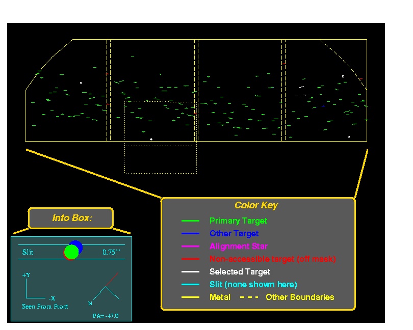
It is important to note that the upper part of the mask has a
semi-circular vignetted region that is not shown in DSIMULATOR.
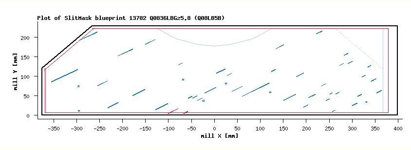
Mask blueprint available in the Slimask
Database after mask submission. Note the semi-circular vignetted
region in the central-upper part of the mask, depicted with a
dotted blue line. Slits should not be placed in the vignetted area
during the design phase.
|
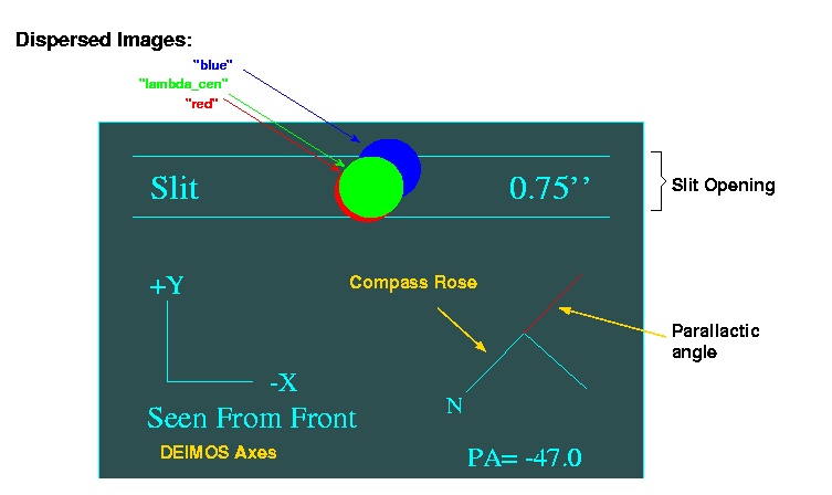
Also, note the information box. In addition to the standard DEIMOS axes
and a compass rose, there is a section of slit (with default slit-width)
shown along with a "dispersed" image, at min, central and max wavelengths.
For convenience, the seeing disk plotted is the same as the slit-width.
This information is useful for deciding acceptable mask PAs to avoid large
slit-losses from atmospheric dispersion:
Keystroke commands
Keystrokes are used for positioning the mask; adding, deleting and
auto-selecting targets; and generating slits. To see available
options, type ?:
DSIMULATOR Command Summary:

     hjkl     translate mask (1" x speed) in the usual vi ways
     p/n      rotate mask (1 deg x speed) in a Pos/Neg sense
      .       cycle through speeds (10, 1, 0.1) for pnhjkl keys
      z       zoom (by abs factor; also 0 reset, -1,...,-5 for CCD1-4,TV fields)
      a       Add a target
      d       Delete a target
      r       Redraw
      i       Clear (initialize) the list of ALL selected objects
      s       Select workable set of objects
      g       generate slits to go over selected targets.
   <space>    print input line of nearest object
      ?       print this list
      q       quit
      I       interrupt task immediately
Procedure
Quick summary of basic mask design
- edit the parameter file for dsim: epar
dsimulator
- update the input and output file
- update the use date (note a date in the past will not
be ingested by the slitmask database).
- update mask coordinates
- update the author and observer information
- change the slit width and slit separation if needed.
- leave the alignment box size as a default 4 arcsec.
- Press s to select a starting set of targets
- us the key board commands above to fine tune target selection.
- Press g to generate slits
- Press q to quit
Details
In normal operation, the user first positions the mask on the sky
using the translation commands (h j k l, in the usual vi sense, to
move the mask on the sky) and rotation commands
(p n, for position and negative rotations). The size of these
moves is controlled by '.', which cycles through fast/medium/slow
speeds (ie, large, medium, small steps).
Next, an "auto-select" ('s') is usually done, as this will try
to maximize the sum of the object priorities without creating
any overlap conflicts. The user may add ('a') or delete ('d')
targets. "Space bar" will print information about the target
nearest the cursor. Also useful here is the 'z' command, which
replots the data centered on the cursor with the absolute zoom
factor specified. There are also some special values defined:
zoom_factor = 0 replots at normal scale; -1, -2, -3, -4 and -5
zoom in on the sections for CCDs 1, 2, 3, 4 and the TV field,
respectively. The standard plot buffer commands, such as Z, P,
E, etc are also useful.
Make sure that alignment stars and at least one suitable guide
star are selected!
When the target selection is made, type 'g' to generate the
slits, which will be overplotted in cyan:
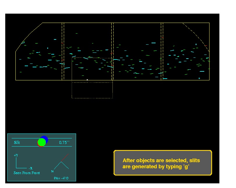
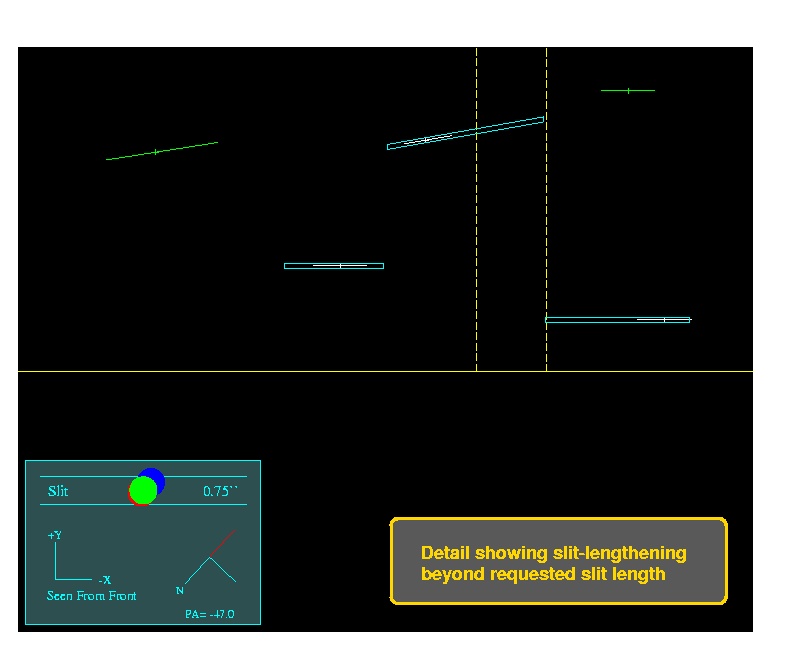
By default, slits are lengthened to where they nearly touch
each other (the slit separation is a parameter, for which 0.5
arcsec is currently recommended). In cases where overlap would
occur, by default the slits are shortened to avoid
overlap. In the plots, both the object (drawn to show the
requested slit length) and the slit appear, so it is immediately
apparent whether slits have been lengthened or truncated.
You can add and delete objects after slits have been
generated; just do another 'g' after the desired modifications.
Note that all selected objects will be given a slit, but
slits may be badly truncated for objects very close to one
another. Also, avoid allowing slits to be lengthened too much
(say over 100 arcsec) -- really long slits may weaken the mask and
cause a jam upon insertion. In these cases, it is best to
create some new targets in empty regions and add them to the input
list; these can be randomly-placed sky slits.
The final step is 'q' to quit, at which point the MDF FITS file
is generated, as well as the output text file and the optional plot file. Note that the
output text file has four sections:
- Mask center (with Guide Field center)
- Selected targets
- TV guide objects, including guider coordinates*
- Non-selected targets
These are all (* the TV section is commented out) in the same
format required for input, so it is easy for the user to, e.g.,
contruct new input lists with only objects that have
not been selected. The first object is recognized as
the field center if it has a field "PA=nnn" in place of
magnitude. Note that this line is also properly formated for
the Keck starlist, provided the colons are replaced with spaces.
Mask submission
After designing your slitmasks, you can submit them for milling.