Field of View
Science Field of View
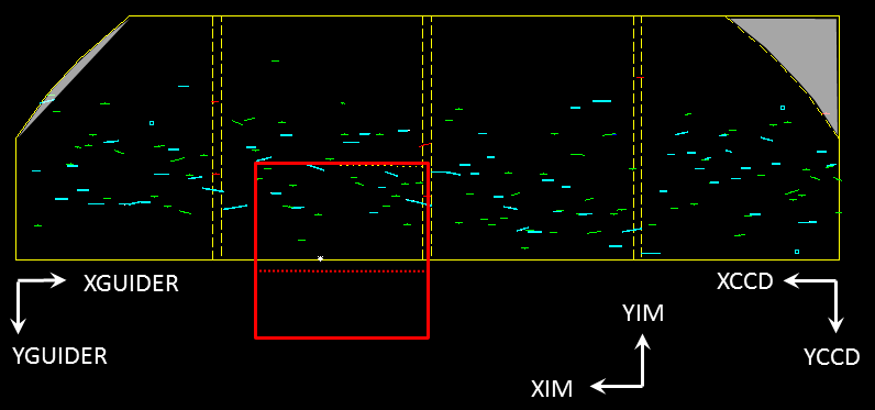
The DEIMOS science field of view is approximately 16 arcmin × 4 armin in size. The diagram below indicates some features of the field of view.
Notes
- The orientation of this view is as seen in the DSIMULATOR program for DEIMOS slitmask design. This is rotated 180° from the DEIMOS ds9 image display.
- The solid yellow line denotes the outline of the metal slitmask area.
- The shaded area at top right is vignetted. Slits should not be placed here.
- The shaded area at top left is outside the legal slit are (being too close to the mask edge). Slits should not be placed here.
- The dashed yellow lines indicate gaps in the CCD mosaic. Spectra from slits placed between these pairs of lines may not fall on the detector.
- The solid red line indicates the outline of the DEIMOS guider field of view. The area above the dotted line is visible as a reflection off the slitmask (when a mask is in place). The area below the dotted line is visible on the fixed pickoff mirror.
Guider Field of View
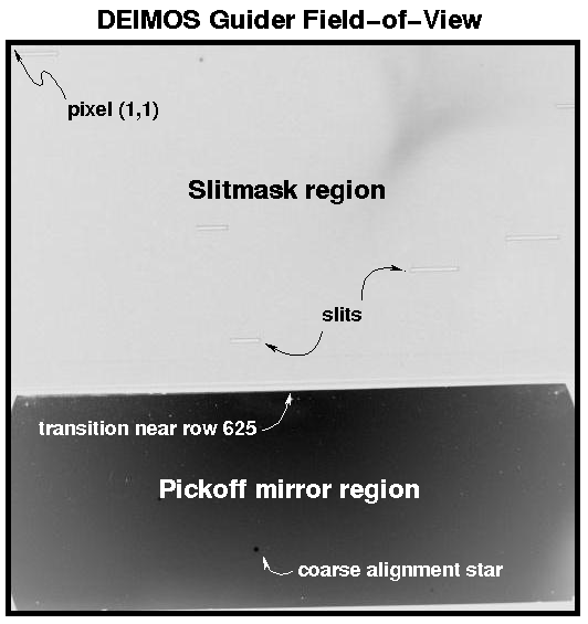
The image below shows the field of view of the DEIMOS guider.
- The orientation of this view is as seen in the DEIMOS MAGIQ display and is identical to the orientation of the image above.
- The bottom 1/3 of the field of view looks at the sky image reflected off of the fixed pickoff mirror.
- The upper 2/3 of the field of view looks at the sky image reflected off of the slitmask. This about 30% as sensitive as the pickoff mirror.
Send questions or comments to:DEIMOS Support