Quick Review
- Launch the SAT
- Load the starlist
- Retrieve DSS images of guider
fields in the afternoon
- Focus the telescope using MIRA if needed
- Slew to target and, while slewing,
configure MOSFIRE to image the alignment slitmask
- Complete Coarse Alignment :
- Select the Target
- Grab Guider Image
- Click on guider star
- Offset telescope
- Complete Fine Alignment:
- Start fine alignment to image the mask
- Send moves
- Repeat Fine Alignment as necessary until moves are small
- Start spectroscopic observations
The Tips and Tricks section covers topics
such as alignment of crowded fields, alignment check for
targets requiring very long (more than 2 hours) integrations and
manually loading old alignment images.
Slitmask Alignment
This checklist describes the procedure for aligning multi-object
slitmasks on MOSFIRE using the Slitmask Alignment Tool
(SAT). Released for use in June 2012 during MOSFIRE
commissioning, the SAT provides a complete set of tools for
aligning slitmasks. Given a properly-formatted starlist, the SAT
predicts guide star locations which may be used to coarse-align a
slitmask. When fine-tuning mask alignment, the SAT displays
graphical fits to objects/boxes in an all-in-one display and makes
recommendations for telescope offsets and rotation. Mask
alignment with the SAT is more efficient than the traditional
command-line and IRAF-based scripts.
To launch the SAT:
- Navigate to an “analysis” VNC desktop (blue background)
- From the window manager background menu select
MOSFIRE Utilities -> Slitmask Alignment Tool
Click on the "Load Star List" button immediately below the
left-hand image the SAT.
WARNING!
The target coordinates in the starlist must correspond to the
center of the mask, accounting for all relative shifts
that may have been applied while designing the masks. To ensure
that the proper coordinates are entered into your starlist file,
generate your starlist
using our custom script for MOSFIRE.
Focusing the telescope before aligning a slitmask should be done
periodically during the night but is not necessary to do before
every mask alignment. We generally recommended re-focusing the
telescope when the telescope elevation angle has changed by
30° or more since the previous focus.
To complete the focus:
- Select target on MAGIQ. On the MAGIQ Observer UI,
locate the line listing your next target in the target list at
the bottom of the window. (Note: this can be done while you
have an exposure in progress) Click the middle mouse button on
that line to highlight it, thus indicating to the OA which
target you plan to observe.
- Select focus star. Ask the OA to locate a suitable
star to run MIRA in the neighborhood of your next target.
The process can take the OA several minutes.
- Queue align mask. Pre-configure the CSU for your
alignment. On the MAGMA UI, click on the name of the next mask
to observe in the Mask Configurations area, then
click on Setup Alignment Mask to queue the moves in
the controller. (Note: this can also be done while the exposure
is in progress)
- Wait for exposure. Wait for your current exposure
to complete.
- Protect detector. On the MOSFIRE Desktop Observing
Mode UI, click on DARK-IMAG mode to protect the
detector from exposure to bright light during your
reconfiguration and telescope slew.
- Slew to focus star. Ask the OA to slew the telescope
to the focus star and run MIRA in the neighborhood of
your new target.
- Confirm safe drive angle. Check the drive
angle shown on FACSUM. If
it is within ±10° of either 0° or 180° (or
any multiple of 180°) then moving the CSU may trigger a CSU fatal error. To avoid
this, have the OA rotate MOSFIRE to a safe drive angle
and execute your CSU move at that rotator position.
- Execute CSU move. On the MAGMA UI, click on
Execute Mask to perform the moves you queued above.
- Wait for mask. Be sure to tell the OA to wait until
your CSU move is completed before launching the telescope focus
routine (MIRA).
- Launch MIRA. Once the mask move is done, ask the OA
to complete MIRA. Wait while the OA completes the focus routine.
Notes
- If you plan to observe the field for two hours (or more),
consider asking the OA to run MIRA one hour west of your target
field in order to represent the midpoint of the exposure.
- MIRA is always run using the J band filter.
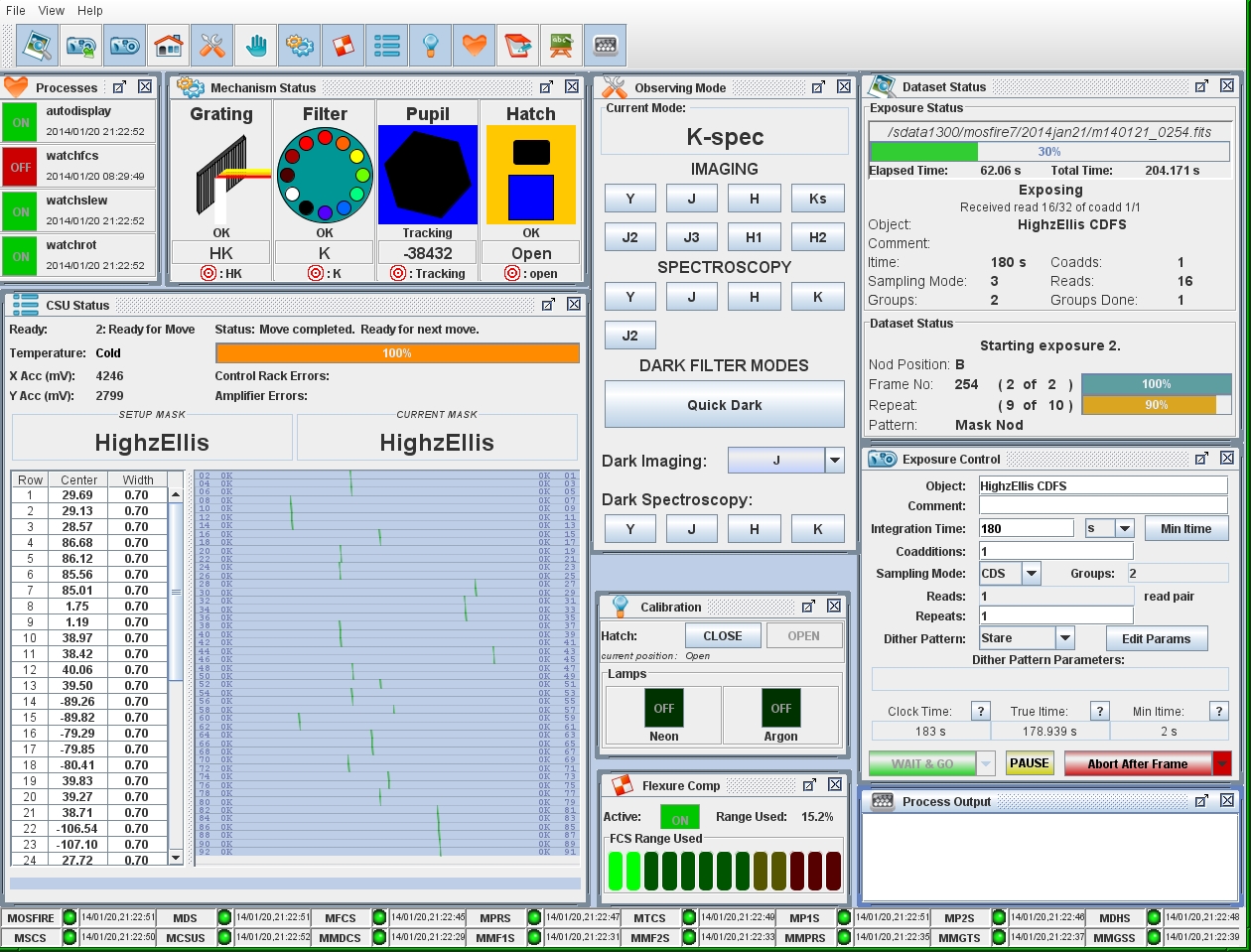
In this phase, we prepare the instrument for mask alignment during
the telescope slew to the science field.
- Click Quick Dark on the MOSFIRE Desktop Observing
Mode GUI.
This will protect the
detector from exposure to bright light during your slew to the
science field. (Note: if you just ran MIRA, then it should have
done this for you).
- Setup Alignment Mask
- Select the new mask in MAGMA
- Click SetupAligment Mask
- Wait for Filter to move to the Dark
- Confirm safe drive angle.
Once the telescope has
reached your target field, check the drive angle
shown on FACSUM. If it is
within ±10° of either 0° or 180° (or any
multiple of 180°) then moving the CSU may trigger a CSU fatal error. To avoid
this, have the OA rotate MOSFIRE to a safe drive angle and
execute your CSU move at that rotator position, then rotate back
to your mask PA to complete the mask alignment process.
- Execute Mask.
Use the MAGMA UI to execute
your alignment mask pattern for the target.
- Optional: Click Dark Imaging: J . This configures the
spectrograph efficiently for J-band imaging, which is the
filter used for imaging the mask.
- Load coarse align. Click the Coarse Align tab on the
SAT.
- Verify pointing. When the OA tells you that your
target is on MOSFIRE, check the following information on FACSUM
to verify that your position is correct:
- Target name and coordinates
- Position angle (skypa)
- Pointing origin (should be MOSFIRE)
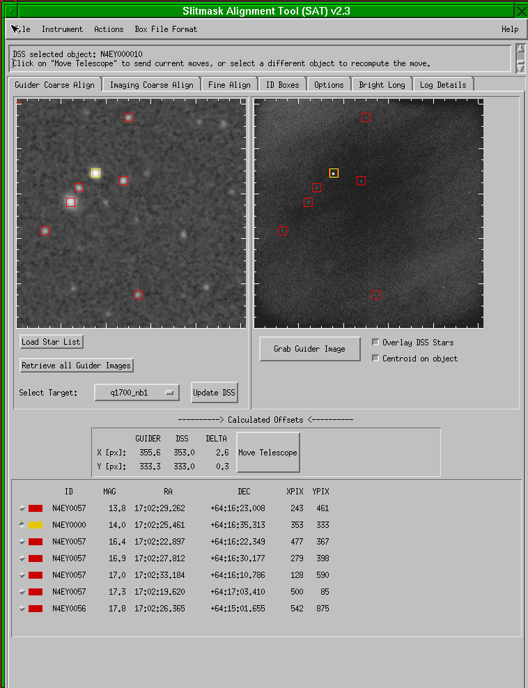
In this phase, we put the stars into the alignment boxes using
the SAT Guider Coarse Align tab.
- Select target. Click the target list selector on
the SAT Guider Coarse Align tab and select the target to observe. By
default, this drop-list displays Current DSS, but you
should select the desired target to trigger SAT to verify your
pointing. This will:
- Download a DSS image of the guider field corresponding
to the science target (unless you did so earlier) and
display the image left side of the pane.
- Overlay red boxes on the six brightest objects
cataloged in the field.
- Populate the table at the bottom of the pane with
object names, celestial coordinates, and predicted guider
positions.
- Erase any existing telescope offsets shown under
Calculated Offsets as a visual cue that offsets are
not calculated, and disable the Move Telescope
button.
- Wait for OA to turn Guiding on
- Grab guider image. Click the Grab Guider
Image button once the telescope is in position. This will:
- Trigger MAGIQ to save an image of the guider field
- Display the guider image on the right image
display
- Overlay RED boxes on the predicted positions
of the alignment objects
- Overlays WHITE boxes on the actual guider
image after analyzing the image using a find asterism
algorythm. White boxes are usually offset from the red boxes.
- Analyze the image to locate the actual images
of the six alignment objects and draw white boxes around
them
- Erase any existing offsets from the screen as a visual
cue that offsets are not calculated
- Disable the Move Telescope button
Observers may adjust the brightness and contrast (if
necessary) by right-clicking on the image and dragging the
mouse.
- Click On Star in Guider image on the right hand side Select an object which is visible in
both the predicted DSS guider image at left and the actual
guider image at right. The SAT will then:
- Measure the position of the object
- Overlay a yellow box on the star to indicate the
selection and centering
- Locate the corresponding image of the object in the DSS
image and toggle the surrounding square yellow
- Toggle the selection indicator from red to yellow in
the table at the bottom of the pane
- Calculate the telescope offsets required to put the
star at the predicted location and display them in the
offsets table below the image
- Enable the Move Telescope button as a visual
cue that moves can be sent
If the SAT highlights the incorrect star in the DSS image,
select a different star either by clicking in the DSS image or
selecting the star in the guide star table.
- Click Move Telescope. This will cause SAT to:
- Offset the telescope
- Acquire and display a new guider image at the updated position
- Verify move. Wait for the guider image on SAT to
update and verify that the stars are in the RED boxes on the right-hand
side guider image now agree. If necessary, click on a new star and send
another telescope move to improve the centering.

In this phase, we refine the positions of the stars within
their respective alignment boxes to achieve optimal
centering of the slitmask using the
SAT Fine Align tab.
- Check that the CSU has finished moving. Wait for the
CSU to finish the alignment mask configuration.
- Optional: Verify the exposure options. The instrument configuration options
set on the SAT Options tab
are appropriate. Unless set to current, these
override the current instrument settings.
- Click Start Fine Alignment button on SAT to start the fine alignment process. The software will then:
- Reconfigure the spectrograph as needed to image the
mask
- Acquire an image of the sky a few arcseconds away to
serve as background subtration.
- Acquire an image of the target.
- Subtract the sky image from the target image and
display the resulting difference image
- Compute and display object and box profile fits
- Calculate offsets in translation and rotation
- Suggest telescope moves by preselecting Y/N for
X/Y offset and rotation moves
- Review fits. For each star the SAT graphs:
- X fit to the stellar and box profiles
- Y fit to the stellar and box profiles
- Residual fit to the object position in the box
on the Fit Residuals plot on the right.
Review the object and box fits, calculated offsets, and move
recommendations.

|
XYFIT codes
| Graphic |
Description |
| White solid line |
Star profile (sky subtracted) |
| White dotted vertical line |
Star center |
| Red solid vertical line |
Predicted star position |
| Green box |
Shows centering of the fitted box |
| Yellow dashed line |
Box profile (object +sky) |
|
- Remove outliers. If necessary, exclude a star from
the fit by clicking the button to the left of the offending
star's graphs. Possible reasons to remove a star from the fit
are:
- No object is visible in the box
- The white dotted line (centroid) is not at the stellar
peak
- The residual displayed in the residual plot is much
greater for one star than for the other targets, indicating
bad astrometry for that star
If you exclude a star from the fit, SAT will recalculate the
moves ignoring that object. Please see the
example image showing a star excluded from the fit.
- Review moves. In the Offsets area, the SAT
displays the recommended moves in X, Y, and rotation. Moves
which are significant are enabled by default, while small moves
are disabled. If you want to override the default move
recommendation, click the Y or N button
next to the offset.
- Send moves.
Reconfigure MOSFIRE for spectroscopy:
- Click Setup Science Mask:
On MAGMA, click Setup
Science Mask to prepare the CSU for moving the
alignment bars to the science position.
- Click Quick Dark mode:
On the MOSFIRE desktop Observing Mode GUI,
select Quick Dark mode (to prevent persistence)
- Wait for filter. Filter should say DARK. The graing may
continue to move.
- click EXECUTE Mask:
On MAGMA, click Execute Science
Mask to prepare the CSU for moving
- Click on the desired Dark spectroscopic mode:(e.g. H )
On the MOSFIRE desktop Observing Mode GUI,
select Dark Spectroscopy: band
(e.g. H) for the spectroscopic mode for your
science. This efficiently configures the filter, grating,
and pupil for your science setup.
- Configure detector.
On the MOSFIRE desktop Exposure Control GUI,
set the exposure and nod parameters:
- Set Integration Time as appropriate (see recommended exposure
times)
- Set Coadditions to desired value
- Set Sampling mode to MCDS
- Set Repeats as appropriate
- Set Dither Pattern to Mask Nod
- Click Edit Params and set nod size to the
appropriate value for the mask
- Wait for CSU mask.
Wait for the CSU move to complete the move.
- Set grating/filter.
On the MOSFIRE desktop Observing Mode GUI,
select the appropriate spectroscopy mode.
- Start exposure.
On the MOSFIRE desktop Exposure Control GUI,
click on Wait & Go button to begin the exposure.
Phew!
Do this step in the afternoon to save time at night:
- Click the Coarse
Alignment tab on the SAT.
- If you have not already loaded the starlist, click Load
Star List, locate the appropriate directory, and select the
appropriate starlist file.
- Click, Retrieve all Guider Images. This will store
FITS images in the data directory for each target in the
list. The FITS data will have names target.fits
- To preview the guider fields, select a target in the target
dropdown list. By default the list shows Current DSS
as the target.
Note: If you modify the coordinates in your target list,
you will need to re-click on Retrieve all Guider Images to
update your guider images.
To specify the sky frame to use for background subtraction
- Select Actions -> Load MOSFIRE Sky Image
- Set all moves to N
- Click Send Moves and Retake Image to trigger a new
image at the current position. It will use the selected
sky image as the sky.
To load an alignment image manually
- Click Actions -> Load Fine Alignment Image.
- If necessary, use the Actions -> Load MOSFIRE Sky
Image to set the sky image to match.
Alignment check
When observations require very long integrations it is recommendable
to perform an alignment check every 2 to 2.5 hours to make sure
targets are still well centered in the slits. This can be done
easily and efficiently with the option Check Alignment in
SAT's Fine Alignment tab.
The procedure to perform an alignment check is as follows:
- Once the current science exposure is close to be completed,
click on Check Alignment. Note it is not necessary to wait
until the last science exposure is completed. Check Alignment
will standby until the current science exposure is finished.
- Once the science exposure is completed, Check
Alignment will automatically:
- Setup and execute the corresponding alingment mask
in CSU.
- Change the observing mode to J-imaging
mode.
- Take an alignment image. Note that no sky image will be
taken. Check Alignment uses the sky image from the
previous alignment.
- Display the results from the alignment algorithm.
- If you are happy with the alignment, then click
on Done: Check Align.
- If the alignment does not look good enough, then you can start an
iterative process using the commands Send Moves and Retake
Image or Send Moves Only, until the mask
is well aligned again. Once you are happy with the
alignment, click on Done: Check Align.
- If the alignment stars residuals are too big, this is
likely due to a bad sky subtraction caused by a strong change in the
sky background since the last alignment. In this case it is
recommendable to Start Fine Alignment, which will take a
new sky image.
- The command Done: Check Align will automatically:
- Setup and execute the corresponding science mask in the
CSU.
- Reconfigure the observing mode to the science observing
mode previous to the alignmemt check.
- At this point you can continue with your science
observations.
For some fields it may be necessary to use guile to fine align a
slitmask due to the density of objects in the field.
Below are some tips and tricks that may be used to
manipulate the software and align a mask.
- When the field is crowded, you may need to acquire a sky
frame manually at a location far away from the field, and then
acquire an on-target alignment image.
- Slew the telescope to a relatively blank field
- Review the options tab to see the current exposure
parameters (typically: CDS mode, 10s, and 2 coadds)
- Acquire a sky frame using MOSFIRE's exposure
control gui
- On SAT select: Actions->Load Mosfire Sky Image, and
select the appropriate sky frame
- Slew to the target and coarse align the mask
- Acquire a science frame by either:
- Acquiring an image using the MOSFIRE exposure
control gui and then click Actions -> Load
Fine Alignment Image. to initiate the
analysis.
- Or set all the moves to "N" and click Send Moves
and Retake Image. This will take an image at
the current location and analyze the data.
- Another option is to simply change the sky nod parameters using the script
nod # #. The default is to take an initial sky image 10 arcsec
east, but you can change the nod throw by updating the
nod parameters. This is helpful if one of the boxes has a
bright star at the "sky" position.
- If necessary, use the Actions -> Load MOSFIRE Sky
Image to set the desired sky image, and then set all
moves to "N" and then click Send Moves
and Retake Image. This will take an image at
the current location and analyze the data.