Quick Review
- Identify Boxes in the afternoon
- Retrieve DSS images of guider
fields in the afternoon
- Focus the telescope using MIRA: if needed
- Slew to target and while slewing
- Configure LRIS to image the slitmask
- Update DSS with target coordinates
- Coarse Alignment
- Grab Guider Image
- Click on guider star
- Offset telescope
- Fine Alignment:
- Click on "Start fine alignment" to image the mask
- Repeat Fine Alignment if necessary.
- Start Spectroscopic Observations .
Slitmask Alignment
This checklist describes the procedure for aligning multi-object
slitmasks on LRIS using the
Slitmask Alignment Tool (SAT).
Released for use in January 2011, the SAT provides a complete set
of tools for aligning slitmasks. Given a properly-formatted
starlist, the SAT predicts guide star locations which may be used
to coarse align a slitmask. When fine-tuning mask alignment, the
SAT displays graphical fits to objects/boxes in an all-in-one
display and makes recommendations for telescope offsets and
rotation. Mask alignment with the SAT is more efficient than the
traditional command-line and IRAF-based scripts. Below are screen
shots of the tool for the three primary observing uses:
To launch the SAT:
- Navigate to an “analysis” VNC desktop (blue background)
- From the window manager pull-down menu select
LRIS Utilities -> Slitmask Alignment Tool
WARNING: The coordinates in the
starlist must be the coordinates for the center of the
mask, accounting for all relative shifts that may have been
applied while designing the masks.
Focusing the telescope before aligning a slitmask is recommended.
The focus is strongly dependent on the LRIS physical rotator
position and the telescope elevation. It is generally recommended
to re-focus the telescope when the telescope elevation angle has
changed by 30° or more, and/or the instrument's
physical rotator position (displayed as
drive on
the FACSUM display) has changed by 40° or more. In practice,
this often means that refocusing is done for each slitmask, since
each mask may have a different rotator position.
To complete the focus:
- Highlight the target in the MAGIQ target list using the
middle mouse button, and ask the OA to slew to the new
highlighted target.
- Ask to OA to run MIRA in the neighborhood
of your target.
Note:
- If you plan to observe the field for two hours (or more),
you may ask the OA to run MIRA one hour west of your target
field.
- MIRA is always run on the blue side.
- While slewing
- Click the Coarse
Alignment tab on the SAT.
- If you have not already loaded the starlist, click Load
Star List, locate the appropriate directory, and select
the appropriate starlist file.
- Select target in the target list, by default this droplist
displays "Current DSS."
- If you did not earlier Retrieve all Guider images,
Click Update DSS on the slitmask alignment
tool to display the DSS image corresponding to the LRIS offset
guider FOV.
- When the OA tells you that your target is on LRIS, check
the following information on FACSUM to verify that your
position is correct:
- Target name and coordinates
- Position angle (skypa)
- Pointing origin (should be LRIS)
In these steps, we put the stars into the alignment boxes.
- Ask the OA to set secPer to 5 or less in order to
provide frequent "full-frame" offset guider image updates. The
SAT needs to read a full-frame guider image and if full-frame
images are not updated frequently, this step will take a long
time.
- On the SAT, click the
Coarse Alignment tab
- Click Grab Guider Image, which:
- triggers MAGIQ to save an image in the nightly
directory, and
- displays the guider image on the right image display.
- Identify DSS stars in guider image.
- Compare the Guider field (at right) to the corresponding
DSS image (at left). The two images should display a
similar stellar field.
- Adjust the brightness and contrast if necessary by
right clicking on the image and dragging the mouse.
- Click on Overlay DSS Stars to overlay predicted star position.
- Click on an object in the guider image (at right). The SAT
will then:
- draw a yellow box at the cursor position;
- draw a corresponding yellow box in the DSS image around
the nearest star in the DSS image
- This star is highlighted yellow in the guide star
list
- The X/Y pixel positions for the GUIDER and DSS images
are displayed in the Calculated Offsets Box.
- The offsets in units of pixels are calculated
and displayed.
- If the highlighted DSS star is not correct, select a
different star by either clicking in the DSS image on the
appropriate star or selecting the star in the guide star
list.
- Click Move Telescope
- Offsets the telescope
- Acquires a new guider image at updated position.
- Optional: Confirm guider move and repeat above steps
if necessary.
In this step, we refine the positions of the stars within
their respective alignment boxes to achieve optimal
centering of the slitmask.
- On the SAT, click on the Fine Align tab.
- Confirm that LRIS is configured for imaging:
- Appropriate slitmask selected
- Correct dichroic in beam
- Click Start Fine Alignment button. The software will
then:
- If the grism is still in beam, removes the grism from
the optical path.
- Set up instrument according to "inst config" tab.
- Acquire a 20 second blue side image.
- Wait for the image to read out.
- Read and analyze image.
- Display object and box profile fits.
- Calculate offsets in translation and rotation.
- Suggest telescope moves by preselecting Y/N for
X/Y-inst and Rotation.
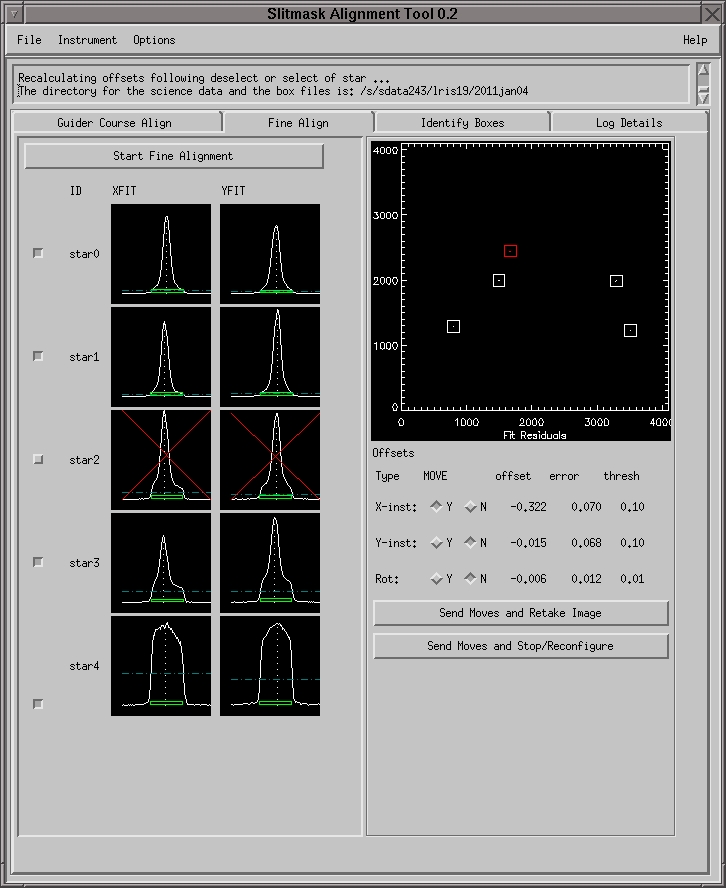
- Review Object and Box fits, calculated offsets, and move
recommendations. For each star the SAT graphs:
- X fit to the stellar and box profile
- Y fit to the stellar and box profile
- Residual fit to the object position in the box
on the Fit Residuals plot on the right.
XYFIT codes
| Graphic |
Description |
| white solid line |
star and box profile |
| vertical white dotted line |
fitted object peak intensity |
| green box |
shows centering of the fitted box |
| blue dashed line |
estimated sky level |
- If necessary, remove a star from the fitting process by
de-selecting the star. Click the button to the left of the
offending star's graphs. Some possible reasons to remove a star
from the fit are:
- The white dotted line is not at
the stellar peak.
- The object is not visible in the box.
- The residual is much greater than the other targets,
indicating bad astrometry for the alignment star.
If you exclude a star from the fit, the offsets will
be recalculated with that object ignored. Please see the
example image of a star excluded from the fit.
- If you want to change a move recommendation,
select the Y or N button next to the offset.
- Send the Moves
- Click Send Moves and Retake Image if moves are
large and a second image is needed to further
fine tune the position.
- OR click Send Moves and Stop/Reconfigure - This
does not yet reconfigure the instrument, so you
need to reconfigure by hand.
- If conditions are variable, it may not be
possible to converge below the threshold limits.
- Reconfigure the instrument for spectroscopy:
- Set dichroic and grism to the appropriate
position for spectroscopy
- Set blue filter to clear position
- Set blue camera focus as appropriate for the
clear position.
- Set exposure time as desired for spectroscopy.
- Expose...phew!
- Click the Coarse
Alignment tab on the SAT.
- If you have not already loaded the starlist, click Load
Star List, locate the appropriate directory, and select
the appropriate starlist file.
- Click, Retrieve all Guider Images. This will store
FITS images in the data directory for each target in the
list. The FITS data will have names "target.fits"
- To preview the guider fields, select a target in the target
dropdown list. By default the list shows "Current DSS" as
the target.
If you adjust the coordinates in your target list, you will
need to reclick on Retrieve all Guider Images to
ensure your guider images are up to date.
Follow these steps to generate the “box files” that
record the locations of your alignment boxes. Please note that
this procedure is typically completed in the afternoon.
- Acquire a set of direct slitmask images via the
LRIS
Slitmask Imaging Tool, as described here.
- Launch the Slitmask Alignment Tool.
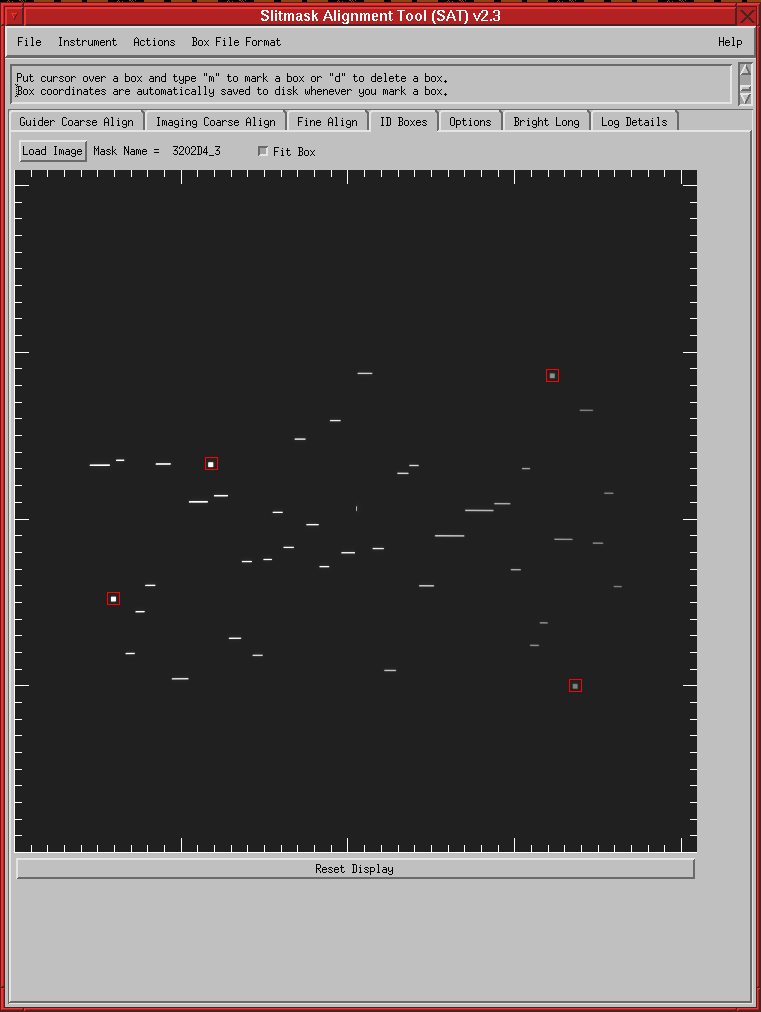
- Click on the ID Boxes
tab on the Slitmask Alignment Tool. Please see the example image of the
identify boxes tab.
- Click Load Image and select
one of your slitmask images. The image will be read from disk
and displayed in the GUI.
- Locate one of your square alignment boxes on the image.
Move the mouse
cursor to the center middle of the box.
- Press the m key to mark the
box. The tool will draw a red square around the box, and will
automatically add the new box coordinates to the box file on
disk.
- Repeat the above step for each box on the mask.
- If you need to delete a box, press the d key to remove the box nearest to the
cursor position. Again, the software automatically updates the
box file stored on disk.
- If desired, verify that the box file was written to disk by
listing the contents of your data directory and verifying that
box files (with a .box suffix) exist.
- Repeat the above steps for additional slitmasks.