| Blue Side | Red side | ||||||||||||||||||
| Type | 2 x 2K x 4K Marconi (E2V) CCDs, backside 15 µm pixels, science grade | LBNL 4k x 4k CCD 500-micron thick deep-depletion 15 µm pixels, science grade (Mark IV, installed in May 2021) | |||||||||||||||||
| Outputs | 4 amplifiers 1,2,3,4 (A,B,C,D old label) | 4 amplifiers L1, L2, U1, and U2 | |||||||||||||||||
| Read noise [e-/rms] Most Recent Measurements |
|
|
|||||||||||||||||
| Conversion Factor[e-/ADU] (Gain). Most Recent Measurements |
|
|
|||||||||||||||||
| Plate scale | 0.135"/pix | 0.135"/pix | |||||||||||||||||
| Bias level | ~1000 ADU | ~1000 ADU | |||||||||||||||||
| Saturation | 65535 ADU | 65535 ADU | |||||||||||||||||
| Linearity | 62,000 ADUs & Saturates at 65,536 ADUs see Linearity page | 59,000 ADUs & Saturates at 65,536 ADUs see Linearity page | |||||||||||||||||
| Bad Pixel Map | Not Mapped | Not Mapped | |||||||||||||||||
CTE @ 40,000 e- CTE @ 200 e- |
|
||||||||||||||||||
| Prepix/Postpix | 4x51=204 real pre image area pixels, 4x80=320 electronically added post image area pixels |
Not Defined Not Defined |
|||||||||||||||||
| Erase time [sec] | 8 | 10 | |||||||||||||||||
| Readout time [sec] | 42 | 90 | |||||||||||||||||
| Shutter time (from trigger to last movement) | ~40 ms | ~60 ms | |||||||||||||||||
| Orientation vs keywords |
When the rotator mode is set to "Position Angle" mode the ROTPOSN keyword may be used to determine the image rotation. ROTPOSN is defined as the rotator user position.
PA = ROTPOSN + 90 These orientations apply only to the LRIS image displays at the telescope. On the blue side the image is rotated 270 degrees and has the x-axis flipped. On the red side, the image is rotated 270 degrees and has the y-axis flipped. The entry below shows the LRIS SPECIFIC ds9 display. |
||||||||||||||||||
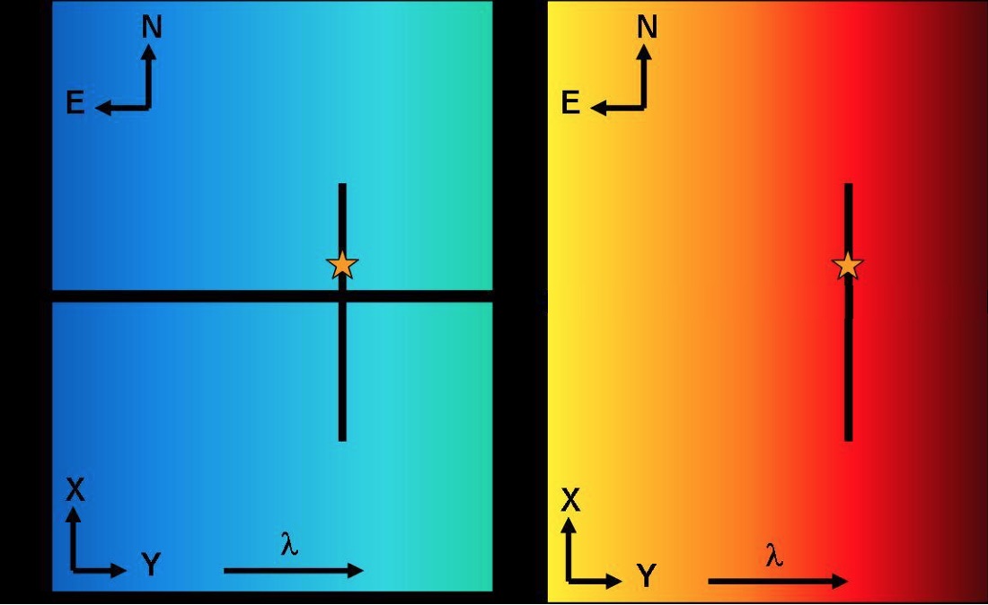
| Orientation on images with PA=0 with the DISPLAY set to the LRIS SPECIFIC ds9 displays |
As seen at the telescope. From top to bottom, blue side amplifiers are numbered 4,3,2,& 1. From top to bottom, red side amplifiers are numbered 3,4,1,& 2.The standard longslit position as indicated by the star in the images is located on amplifier 3 on the blue side and on 4 for the red side. Click on the image to enlarge |
||||||||||||||||||
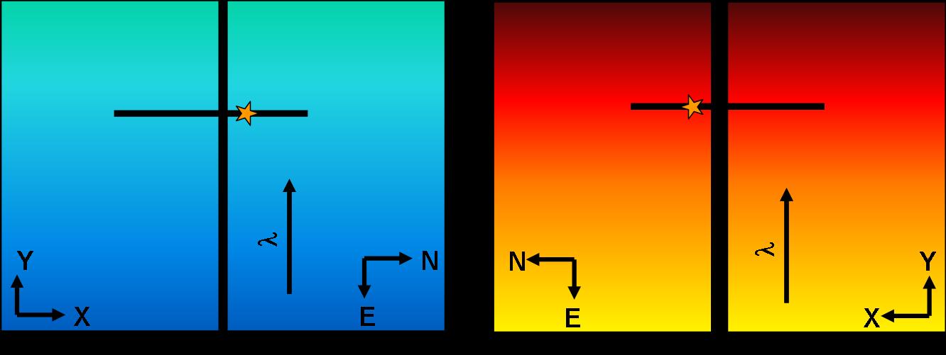
| Orientation on images with PA = 0 and DISPLAY set to a normal ds9 display (no rotations or flips) |
Shows the LRIS images without rotations or flips. Click on the image to enlarge |
||||||||||||||||||
| Windowing/Binning | See binning and windowing page for details | Not Implemented | |||||||||||||||||