Introduction
This page describes the coordinate systems relevant to DEIMOS observations as well as the different angles that are used to define the orientation of the DEIMOS detector on the sky.
DEIMOS Coordinate Systems
When we look at the DEIMOS detector, the spatial direction is along the detector rows and the spectral direction is along the detector columns. In direct imaging mode, the X axis is along the detector rows, positive to the right, and the Y axis is along the detector columns, positive up. This creates confusion when it comes to the question of what is the instrument axis most appropriate for the users. In the case spectroscopy, it makes sense to define the instrument reference axis along the detector rows, i.e. along the slits. This will ensure that in Position Angle mode, PA=0 aligns the slit with the North-South direction and in Vertical Angle mode, V=0 aligns the slit with the parallactic angle. However, in the case of direct imaging, it makes sense to define the reference instrument axis along the detector columns, so that in Position Angle mode, PA=0 aligns the detector columns with the North-South direction.
Since DEIMOS is mostly used as a spectrograph, the user angle (UA) is defined as the angle of the detector rows relative to the celestial North. UA will be the PA when the rotator is in Position Angle mode, V when the rotator is in Vertical Angle mode and r when the rotator is in stationary mode (see section on DCS coordinate systems).
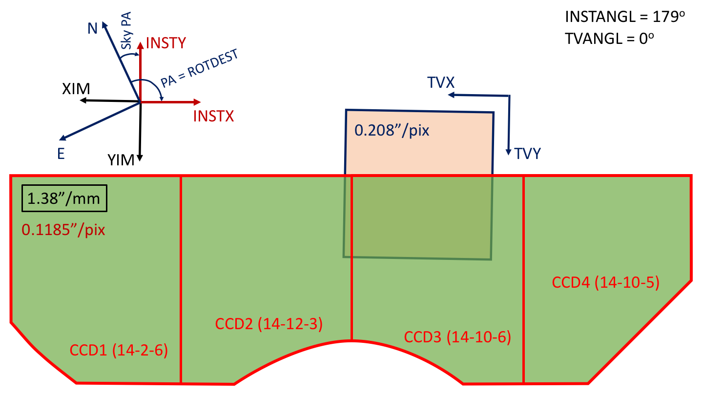
The following figure illustrates the relative orientation of the different coordinate systems for DEIMOS, assuming an observation in Position Angle mode (UA = PA fixed with respect to the North).

|
| Figure 2. Coordinate systems relevant to DEIMOS operations. |
Note that there is a 179 deg rotation (INSTANGL) between the Instrument Coordinate system and the Pointing Origin Coordinate system. The TV coordinate system has the same orientation as the Pointing Origin Coordinate system (TVANGL = 0).
The PA defined in the previous image is the same as the PA defined in DSIMULATOR. This is the angle that should be defined as ROTDEST in the target list. Note that we have arbitrarily depicted a negative PA to make the diagram more general. It is important to bear in mind that the definition of ROTDEST in DEIMOS looks different in Figure 1 than in Figure 2, because the most appropriate instrument axis is along the slit, i.e. along the detector rows (positive INSTX).
In the case of MOS observations, we have a Python script that can be used to create the target list automatically from the DSIMULATOR output files. This tool will define ROTDEST always positive, i.e. if the PA defined in DSIMULATOR is negative, it will add 360 degrees to ROTDEST.
When the observations are done with the rotator in PA mode, FACSUM will report the Sky PA = ROTDEST + 90, which is the angle between the science detector columns and the celestial North.
The ROTDEST keyword in the DEIMOS image headers differs by 90 degrees with respect to the ROTDEST in the target list: ROTDEST(FITS) = ROTDEST(TARGETLIST) - 90. This makes the ROTDEST definition in the FITS header consistent with the general definition of PA shown in Figure 1 and through the KSD40 document. The definition of ROTDEST in the FITS header is the angle of the YIM axis relative to the North.
Finally, in order to have the elevation aligned with a standard DEIMOS longslit, observers should request a ROTDEST = -90 or 90 in Vertical Angle mode.
DCS Coordinate Systems
The definitions of the different coordinate systems and angles are extracted form the KSD40 technical document. Some of the figures contained in the KSD40 document are also illustrated here for convenience.
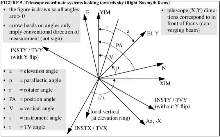
DEIMOS is located on the Right Nasmyth focus of the Keck II telescope. The following figure shows the coordinate systems and relative orientation between them for any instrument mounted on the Right Nasmyth focus.

|
| Figure 1. Coordinate systems on the Right Nasmyth focus. (Figure extracted from KSD40). |
The coordinate systems in Figure 1 are defined as follows (see KSD40 for a detailed explanation):
The angles shown in Figure 1 are defined as follows:
- Elevation angle (a): Angle of the elevation axis relative to the local vertical at the elevation ring.
- Parallactic angle (p): Angle of the elevation axis relative to the celestial North.
- Rotator angle (r): Angle of the YIM axis relative to the local vertical at the elevation ring.
- Position angle (PA): Angle of the YIM axis relative to the celestial North.
- Vertical angle (V): Angle for the YIM relative to the elevation axis.
- Instrument angle (i): Angle of the Pointing Origin Coordinate System relative to the Instrument Coordinate System. This should be a fixed for a given instrument.
- TV angle (t): Angle of the Pointing Origin Coordinate System relative to the guider TV Coordinate System. This should be a fixed for a given instrument.
The instrument rotator can be in any of the following three tracking modes:
- Position Angle mode: The YIM axis is maintained at a fixed position angle (PA) relative to North.
- Vertical Angle mode: The YIM axis is maintained at a fixed vertical angle (V) relative to the vertical (Elevation axis).
- Stationary mode: The rotator is stationary at a fixed rotator angle (r).
The rotator therefore requires just two parameters, a user angle (ROTDEST keyword) and a tracking mode (ROTMODE keyword). The interpretation of ROTDEST is a function of the mode, which in the case of the Right Nasmyth focus is:
| Tracking mode | User angle (UA) | Rotator angle (r) |
|---|---|---|
| Position angle | PA | UA - p - a |
| Vertical angle | V | UA - a |
| Stationary | r | UA |
The following keywords are used to define some of the relevant rotator angles:
- EL: Elevation (a).
- FOCALSTN: Current focal station.
- PARANG: Parallactic angle (p).
- ROTDEST: Desired user angle (UA).
- ROTMODE: Rotator tracking mode.
- ROTPDEST: Desired physical rotator angle (r).
- ROTPOSN: Achieved user angle (UA). When the rotator is tracking, this value should be close to ROTDEST.
- ROTPPOSN: Achieved physical rotator angle (r). When the rotator is tracking, this value should be close to ROTPDEST.
- INSTANGL: Instrument angle (i).
- INSTFLIP: Indicates whether an instrument Y flip is necessary.
- TVANGL: Guider angle (t).
- TVFLIP: Indicates whether a TV Y flip is necessary.
Send questions or comments to:DEIMOS Support