DEIMOS Changeouts

Contents


Tools & Supplies

Bring the following tools to the Keck II Nasmyth deck in preparation for performing the instrument reconfiguration:
  • Printout of the DEIMOS reconfiguration off of the Summit Instrument Activity Schedule (SIAS)
  • Flashlight
  • large flathead screwdriver (near handpaddle)
  • 3/16" T-handle wrench (on leash near the handpaddle)
  • 5/32 Bondhus wrench
  • DEIMOS slitmasks from the instrument lab
  • DEIMOS filter box (may already be on the deck beside the instrument)
  • DEIMOS slitmask alignment tool

Grating Changeout Procedure

  1. Rotate instrument into position:
    • Release the band brake at the front left of the instrument.
    • Locate the instrument handpaddle on the right side of the instrument.
    • Set the bottom switch to Manual mode.
    • Set the Mode switch to 2.
    • Set Position switch to 3 for grating access.
    • Press and release FWD button to rotate instrument to the filter changeout position.
    • Set the band brake at the front left-hand side of the instrument to protect the drive box from stress during the changeout.
  2. Open the access door:
    • Unlock the grating access door by turning the flathead screw 1/2 turn CCW.
    • Grasp the handle and pull down to open the access door.
    • Note that the Hatch Open LED on the handpaddle turns ON.
  3. Locate the grating pushbutton panel inside the access hatch at the top right.
  4. Press the appropriate button (3 or 4) to bring the desired grating to the unload position. The grating should unclamp (producing a loud click), and the grating box should move to the desired position. The grating will then be rotated to the unload position, at which point you should get a green LED lit on the pushbutton panel. The entire process takes about two minutes. Occasionally, the move will fail and the yellow LED will remain on. It is then necessary to press the desired button one more time. If this still does not produce success, contact instrument support for assistance.
  5. Take a grating cover from the storage slot on the instrument. Note that there should be two covers in the storage slot when you start. Insert the grating cover into the slot in the slider until it stops. Note that the "lip" on the grating cover should point to the left.
  6. Unscrew the tricky captive screw on the grating mount:
    • Insert the 3/16" T-handle hex wrench into the screw head.
    • Turn the screw CCW 3 turns until it spins loosely.
    • The L-shaped flap onto which this screw mounts should then flip down toward you.
  7. Loosen the two remaining captive screws on the grating mount:
    • Insert the 5/32 Bondhus wrench into the screw head.
    • Turn screw CCW until it stops turning.
    • Repeat for second screw.
  8. Remove the grating from the slider:
    • Grasp the grating mount handle with your left hand.
    • Pull the handle to your left to unseat it from the slider.
    • Carefully pull the grating toward you so that it slides along the channel in the slider. Watch out for the pinch point.
    • Remove the grating from the instrument.
  9. Exchange gratings:
    • Return the removed grating to the grating storage cabinet near the elevator.
    • Select the new grating to be inserted frm the cabinet and bring it to the instrument.
  10. Insert the new grating into the instrument:
    • Orient the grating so that the cover faces to the left.
    • Seat the grating into the slots in the slider and push it in until it stops.
    • Push the handle to the right (toward the front of the instrument) to seat it fully.
  11. Attach the tricky captive screw on the grating mount:
    • Insert the 3/16" T-handle hex wrench into the screw head.
    • Flip the flap up into position.
    • Turn the screw CW 2-1/2 turns until it is snug.
  12. Tighten the two remaining captive screws on the grating mount:
    • Insert the 5/32 Bondhus wrench into the screw head.
    • Turn screw CW until it it snug.
    • Repeat for second screw.
  13. Remove the grating cover from the grating.
  14. Verify that the green LED is lit. If not, you'll need to press the button again to get the grating back to the unload position in order for the scanner to work.
  15. Holding the barcode scanner at the door, scan the barcode label on the grating. Verify that the instrument responds with a beep followed by a honk. NOTE: if the barcode label on the grating is damaged or unreadable, you can scan one of the grating barcode labels on the sheet attached to the instrument. However, please scan the label on the grating itself whenever possible in order to ensure that the correct label is scanned.
  16. Repeat procedure for additional grating if needed.
  17. Close the hatch:
    • Grasp the handle on the door and pull up to close the access door.
    • Lock the grating access door by turning the flathead screw 1/2 turn CW.
    • Note that the Hatch Open LED on the handpaddle turns OFF.
  18. Verify that there are still two grating covers in the storage slot! If not, you may have forgotten to remove one from a grating.

Filter Changeout Procedure

  1. Rotate instrument into position:
    • Release the band brake at the front left of the instrument.
    • Locate the instrument handpaddle on the right side of the instrument.
    • Set the bottom switch to Manual mode.
    • Set the Mode switch to 2.
    • Set Position switch to 5 for filter access.
    • Press and release the FWD button to rotate instrument to the filter changeout position.
    • Set the band brake at the front left-hand side of the instrument.
  2. On the filter access door, unclip the latch, and slide the door up. Note that the Hatch Open LED on the handpaddle turns on.
  3. Consult the SIAS printout and determine the first filter to change.
  4. On the filter wheel button panel to your left, press the number of the filter position to change out.
  5. Remove a filter handle from the right side of the filter box and attach it to the filter to be removed from the filter wheel by screwing the thumbscrews by hand. Do not overtighten!
  6. Grasp the handle and pull carefully but firmly to disengage the filter from its detent and slide it out of the wheel.
  7. Place the filter into the filter box, leaving a gap between it an any adjacent filters if possible. Unscrew the handle from the filter.
  8. In the filter box, locate the filter to be inserted into the filter wheel.
  9. Attach the handle to the filter and carefully remove the filter from the filter box.
  10. Insert the filter into the open slot in the filter wheel, making sure that the arrow on the filter holder points to your left (i.e., in the direction the photons would travel to reach the detector).
  11. Push the filter into the wheel until it clicks into the detent. Verify that the filter frame is flush with the wheel and does not protrude.
  12. Remove the handle from the filter frame.
  13. Press the position switch to re-select the current position.
  14. Wait for the position switch on the button panel to turn green.
  15. Take the bar code scanner and scan the barcode label on the filter you just inserted into the filter wheel. Verify that the instrument responds with a beep followed by a single, long honk.
    • NOTE: if you get a beep followed by three short honks, an error has occured. The most likely problem is that the filter wheel is not centered on the desired position. In this case, the green light on the filter wheel is not lit; press the appropriate button on the filter selector panel to return the desired position.
    • NOTE: if the barcode label on the filter is damaged or unreadable, you can scan one of the filter barcode labels on the sheet attached to the instrument. However, please scan the label on the grating itself whenever possible in order to ensure that the correct label is scanned.
  16. Repeat these steps for additional filters to be changed.
  17. Close and latch the access door. Note that the Hatch Open LED on the handpaddle turns OFF.

Slitmask Changeout Procedure

  1. Inspect all masks to ensure that they are acceptable for installation. In particular, check that the masks:
    • have the same shape (by laying them on top of each other);
    • have the notch cut out along the bottom edge;
    • have the circle cut out along the bottom edge;
    • are reasonably straight, with no more than one inch of warp from side to side
    If a mask does not meet these criteria it may jam or otherwise cause problems during mask loading, so do not load it!
  2. Rotate instrument into position:
    • Release the band brake at the front left of the instrument.
    • Locate the instrument handpaddle on the right side of the instrument.
    • Set the bottom switch to Manual mode.
    • Set the Mode switch to 2.
    • Set Position switch to 4 for slitmask access.
    • Press and release the FWD button to rotate instrument to the slitmask changeout position.
    • Set the band brake at the front left-hand side of the instrument to protect the drive box from stress during the changeout.
  3. Open the access door:
    • Unlock the slitmask access door by turning the flathead screw 1/2 turn CCW.
    • Grasp the handle and pull down to open the access door.
    • Note that the Hatch Open LED on the handpaddle turns ON.
  4. Move the slitmask cassette to the load position by pressing the POSN 1 button on the cassette.
  5. Insert the DEIMOS slitmask alignment tool atop slitmasks and slide to back of carriage. Note: take care to avoid pulling the bundle of wires in the slitmask area!
  6. Loosen the 2 thumbscrews on the cassette door and flip the door down towards you to allow access to the masks.
  7. Consult the SIAS printout to determine which masks to remove. (Note that the first occupied slot is position 2, not 1!) Remove all of the masks marked for replacement and set them aside on a cart.
  8. Insert the new masks, verifying that the barcode number on the mask matches that on the SIAS printout.
  9. Important notes:
    • Verify that all masks are reasonably straight. Masks which curve more than 1 inch to the left or right must be manually "uncurled" or they will probably jam and cause a major headache.
    • Verify that masks are not cross-threaded; i.e., that no mask crosses over into an adjacent slot. Note: if you used the slitmask alignment tool as recommended above, the masks will not be cross-threaded.
  10. Flip the cassette door up and verify that slits align to the comb. Verify that slots 1 and 13 are not occupied! Tighten the 2 thumbscrews on the cassette door.
  11. Slide mask alignment tool forward to cassette door and remove, taking care to avoid pulling on the bundle of wires. If tool binds when sliding forward, this indicates that a mask has been cross-threaded!
  12. Verify that the comb is aligned with the cassette door. The comb should be flush with door edges. Note: Visual detection is difficult, recommend using fingers.
  13. Close the access door:
    • Grasp the handle and pull up to open the access door.
    • Lock the slitmask access door by turning the flathead screw 1/2 turn CW.
    • Note that the Hatch Open LED on the handpaddle turns OFF.
  14. Initiate slitmask scanning by picking up the barcode scanner and scanning the SCAN MASKS item on the COMMAND sheet.

Cleanup

  1. If no new slitmasks are to be scanned, scan the COMMIT barcode with the scanner to update the instrument configuration. NOTE: doing so will cause the motor control software to be stopped and restarted; hence, do not attempt any motor moves for at least 2 minutes after scanning COMMIT!
  2. Release the band brake.
  3. Set the switch on the handpaddle to Computer mode.

Verification -- Running DREMEL

  1. Return to the control room and launch the DEIMOS control GUI if it is not already up.
  2. If new slitmasks were installed, complete the slitmask scanning process as described below:
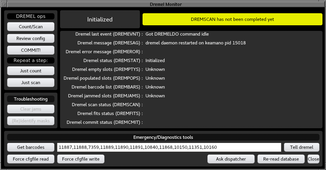
    • Click on the DREMEL Details... button to launch the DREMEL monitor panel.
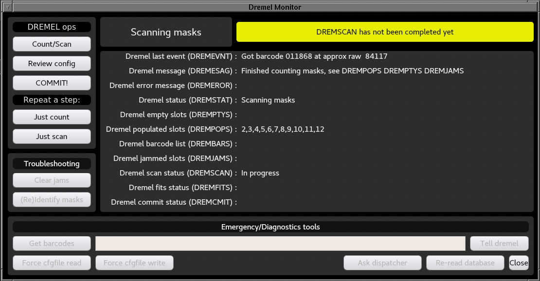
    • If slitmask scanning is required and was not already initiated at the Nasmyth deck, click on the Count/Scan button to count and scan masks.
    • Wait while the software makes an initial pass to test all slitmasks by inserting each one in turn, and then a second pass (in the reverse direction) to read barcodes. The process should take about 13 minutes.
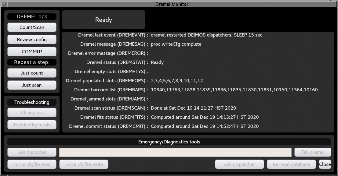
    • When scanning is completed, DREMSCAN will read, for example:
      	Done at Sat Dec 19 14:11:27 HST 2020
    • Compare the list of scanned barcodes (DREMBARS field) to the expected list on the SIAS printout to verify that the proper slitmasks were installed.
    • Verify that the DREMJAMS field is empty, indicating that no slitmasks jammed during the count phase. If jams occurred, ask summit tech to investigate whether slitmasks were cross-loaded in the cassette.
    • If scanning succeeded, the software will then generate the FITS database files. When completed, DREMFITS will read, for example:
      	Completed around Sat Dec 19 14:13:27 HST 2020
    • Click Review Config to launch a tkremel popup window which shows the configuration which will be registered when you commit the changes. NOTE: this GUI occasionally lies on the first attempt; if the configuration does not seem to have changed, kill the tkremel popup by clicking its Quit button, then click Review Config once more. If the pending configuration changes shown this new tkremel popup window are correct, then click its Quit button and continue to the next step. If not, you have a problem and need to investigate further.
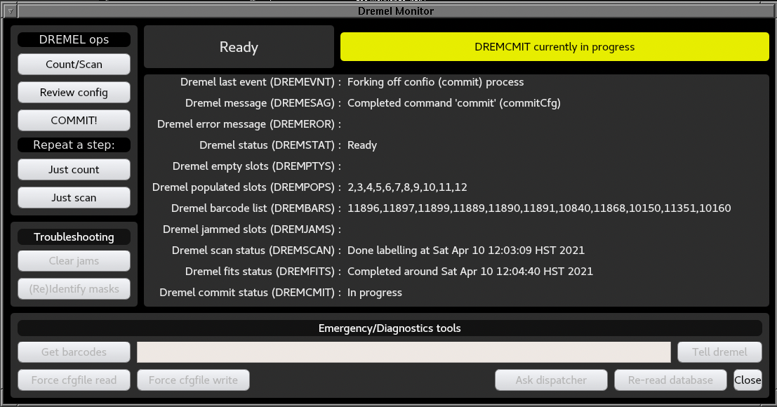
    • When you are convinced that the pending changes are correct, effect the change by clicking on COMMIT!. This will cause the database to be updated and the dispatchers to be restarted, and takes about one minute to complete. When finished, DREMCMIT will read, for example:
      	Completed around Fri Sep 06 14:42:51 HST 2002
  3. Shutdown and restart the Dashboard GUI.
  4. Double-click on the SLITMASK box to view the slitmask panel. Verify that the slitmask names (which are displayed in reverse order match the observer's request on the SIAS printout. If any names are UNKNOWN, see instructions below.
  5. Double-click on the GRATING box to view the grating panel. Verify that the gratings in positions 3 and 4 match the observer's request on the SIAS printout.
  6. Double-click on the FILTER box to view the filter panel. Verify that the filters match the observer's request on the SIAS printout.

Notes

  • When to COMMIT. Scan or click on COMMIT only after all filters, gratings, and slitmasks have been changed out, scanned, and DREMELED. Running COMMIT takes several minutes and causes the motor control software to be stopped and restarted, so it should only be done at the end of a session. Specifically, if you COMMIT while DREMEL is scanning masks, the slitmask cassette will stop moving and DREMEL will fail! In this case, you may need to call for help in order to get DREMEL restarted.
  • When to use alternate barcodes. Each filter and grating has a barcode on it which uniquely identifies it. In case these are damaged or lost, a laminated sheet taped to the instrument provides substitute barcodes that can be used. Use these only if the original barcodes are not usable. If a barcode is damaged, then do the following:
    • Open the access hatch (filter or grating) as if you were going to scan the barcode on the filter or grating.
    • Scan the appropriate substitute barcode.
    • Verify that a beep/bonk sequence is received.
    Note that the substitute barcodes will not work if the appropriate access hatch is closed. This is a safety feature to prevent accidental scanning of barcodes.

Troubleshooting

  • Jammed slitmasks. TBD.
  • Unknown masks. If a reported slitmask name is of the form UNKNOWNn, then the database does not have knowledge of the barcode number. It is first necessary to contact De Clarke at UCO/Lick to sync up the databases. Then one must select the dremel command readDB to re-read configuation information, then commit, restart dispatchers, restart Dashboard, etc.

A Sample DREMEL Session

Here is a detailed description of a typical DREMEL session in which slitmasks are scanned and the resulting configuration is committed.
  1. The starting state for DREMEL. This is what the screen should look like when you begin a DREMEL session:
    DEIMOS DREMEL GUI initial state if the last time DREMEL was run, it ended successfully.
    It is also possible to find the DREMEL GUI in the following state if the dremel service was restarted sometime before launching the GUI:
    DEIMOS DREMEL GUI initial state if the the dremel daemon was restarted before opening the GUI.
  2. Launch Count/Scan. Click on the Count/Scan button to start the slitmask process. The following should happen on the GUI:
    • Top message changes to Counting Masks.
    The software will now start cycling through all slitmask positions, attempting to insert and retract each mask. This verifies which mask slots are occupied and which are empty, and also tests whether slitmasks jam.
    DEIMOS DREMEL GUI while counting and scanning the slitmasks.
  3. Verify counting. When the count is completed, the software reports it progress:
    • DREMPTYS lists any slots which don't have masks.
    • DREMPOPS lists all slots populated with masks.
    • DREMJAMS lists any slots in which slitmasks jammed. See troubleshooting notes above if any masks jam!
  4. Start scanning. If you scanned SCAN MASKS at the instrument or clicked Count/Scan on the GUI, DREMEL will start scanning barcodes automatically as soon as counting is done (assuming no errors were encountered). If you clicked Just Count, then you need to click on Just Scan to initiate the scanning process. DREMEL will turn on the barcode scanner and begin reading mask barcodes.
    • The top message reads Scanning masks.
    • DREMSTAT reads Scanning masks.
    • As each mask is scanned, the DREMESAG keywords reads
      Got barcode XXXX at position YYYY
      indicating a successful scan.
  5. Verify scanning. After all barcodes have been scanned, the normal result is:
    • Top message reads DREMFITS date is earlier than DREMSCAN
    • DREMSCAN reads Done at (date)
    • DREMESAG reads Completed command 'scan' (scanMasks)
    • DREMBARS contains the list of scanned barcodes, which should contains the same number of items as the DREMPOPS list.
    You may also notice messages about the FITS writer being started; this is normal.
  6. Review configuration. Before committing changes, verify that what you put in is what was called for on the SIAS. Click on Review Config to review the list.
    • Check the filters, which are listed on the top menu.
      DEIMOS DREMEL GUI review filter configuration.
    • Click on the Gratings tab and check the gratings.
    • Click on the Mask tab and check the slitmasks.
    Note: you will usually get old information on the first attempt. If so, simply click on the Quit at the bottom of the tkremel popup to dismiss the tkremel window, and click Review Config again on the dremel panel to bring it up again. If information still doesn't match, then something went wrong in the DREMELing process.
  7. Commit changes. Complete the reconfiguration by clicking on COMMIT. This will cause the new configuration to be written into a log file, and the motor control software to be restarted so that it re-reads the logfile and knows which elements are in which positions. The GUI gives the following feedback:
    • DREMEVNT reads "Forked off confio (COMMIT) process".
    • DREMESAG reads "Completed command 'commit' (commitCfg)"
    • DREMCMIT reads "in progress" and then goes to "completed around (date/time)".
    DEIMOS DREMEL GUI while the configuration is begin committed.
Last modified: 06/19/2021 09:25
Send questions or comments to:DEIMOS Support

The information on this page is the property of the W. M. Keck Observatory. The contents of this page or any part thereof shall not be copied or otherwise reproduced or transferred to other documents or used or disclosed to others for any purpose other than observing support at the W. M. Keck Observatory and the subsequent analysis and publication of scientific data obtained from observations conducted at the W. M. Keck Observatory. All rights reserved. © W. M. Keck Observatory.