IMPORTANT NOTES:
- SMDT does several checks to make sure that the mask design is correct. However, observers should always check the sanity of the mask design after submitting the design to the Slitmask Database, in order to make sure that the final mask design is correct.
Background
LIKE DSIMULATOR, with SMDT observers interactively select a set of science targets and distribute slits across the mask so that the spectra will not overlap. You will also identify two sets of stars to be used for mask alignment:- Coarse alignment stars establish the approximate alignment of the mask and must be lie within the DEIMOS guider field of view.
- Fine alignment stars enable precise adjustment of the instrument rotation and telescope position to center your science targets within their slits. Such stars can lie anywhere within the DEIMOS science camera field of view.
SMDT generates several kinds of output, including:
- FITS binary table that are uploaded via the UCO/Lick slitmask submission system for eventual milling at the Keck summit
- PNG plot of the mask layout
- ASCII output file listing the selected and non-selected targets which is used to generate guider finder charts
Download and Running
Basic installation
Follow these steps to download and run the SMDT software:- The SMDT software can be found on the Keck github .
The software can be downloaded with a git clone.
git clone https://github.com/KeckObservatory/smdt.git
- Check the requirements.txt file and install any missing dependences.
Running the software
Go into the smdt directory.python app.pyThis should launch the SMDT software in your default web browser..
Target List
The key input for SMDT, like DSIMULATOR is the catalog of possible targets. You will supply this catalog in the form of an ASCII file with one line per target. There are 7 required fields followed by several optional fields, as shown in this sample intput catalog.
| Column | Field | Description | Datatype | Units | Example |
|---|---|---|---|---|---|
| Required Fields | |||||
| 1 | Object Name | Currently limited to 16 characters. No whitespace allowed. |
string | Cl0016+16_gal276 | |
| 2 | RA | Right Ascension | real | sexagesimal hours | 00:16:00.000 |
| 3 | Dec | Declination | real | sexagesimal degrees | +16:00:00.00 |
| 4 | Equinox | Equinox of RA/Dec coordinates | real | year | 2000.0 |
| 5 | Magnitude | Brightness of target | real | mag | 21.50 |
| 6 | Passband | Filter in which the brightness was measured | string | V | |
| 7 | Pcode | Priority code: indicates target type and relative weighting of science targets as indicated below. | integer | 1000 | |
| Optional Fields | |||||
| 8 | Sample | Sample to which the object belongs. When auto-selecting, objects in Sample 1 are selected first; remaining space is then filled with Sample 2, then Sample 3, etc. Default=1. | integer | 1 | |
| 9 | Select | Flag indicating whether to pre-select the target. If non-zero, object is pre-selected. This is useful for objects that you definitely want to appear on the mask, eg, extremely high-priority objects, or e.g., a set of useful alignment stars. Default=0. | integer | 0 | |
| 10 | SlitPA | Position angle of the slit | real | degrees | 180.00 |
| 11 | Len1 | Requested length above object (in direction of PA) | real | arcsec | 4.0 |
| 12 | Len2 | Requested length below object (opposite to PA) | real | arcsec | 4.0 |
| 13 | SlitWidth | Desired slit width. Not implemented, so this value is ignored. Slit width is set globally by the input parameters. | real | arcsec | 1.5 |
Priority codes
- positive values act as weights in selection of program targets (i.e., priority = 1000 has twice as much weight for selection as priority = 500);
- -1 indicates a guide star;
- -2 indicates an alignment star;
- 0 should not be used
- others ignored
Mask design considerations
Selecting coarse alignment stars
Coarse (initial) alignment of the DEIMOS mask on-sky is accomplished by identifying stars in the DEIMOS guider and placing it at the position indicated on the finder chart you'll generate at Keck using the deimos_guider_dss software.DEIMOS observers must consider these characteristics when selecting guide stars:
- Quantity. Please select 3-5 possible alignment stars if possible. Relying on a single star is asking for trouble, since it could fall in a bad place (e.g., near an edge or on the border between mask and mirror).
- Placement. The DEIMOS guider field of view consists of two parts, one viewing the pickoff mirror and one the reflected sky off the slitmask. The pickoff mirror, which covers about 1/3 of the field of view, is the preferred place to position your coarse alignment star. Stars can also be placed on the slitmask region, but it is only about 30% reflective and so stars seen there will be somewhat dimmed. If possible, avoid choosing a star near the break between the mirror and slitmask. If multiple coarse alignment stars are available, it's definitely wise to select several in case one presents problems.
- Brightness. Your coarse alignment stars should be in the 15<R<18 magnitude range. Fainter stars become increasingly difficult to identify and may only work in excellent atmospheric conditions. If possible, it is preferable to guide on stars on the brighter end of the range. If stars on the fainter end of the range are selected, it is strongly recommendable that they are placed on the guider's pickoff mirror rather than reflected off the slitmask.
Selecting fine alignment stars
Fine alignment of the DEIMOS mask with the science targets is accomplished by centering selected stars within square alignment boxes milled into the slitmask. By default, SMDT will create boxes of size 4×4 arcsec, and you should use this recommended size. Further recommendations:- Select isolated (non-double) stars in the brightness range 15 <= R <= 20 for your alignment boxes.
- We strongly recommend selecting at least 2 stars toward each end of the mask (i.e., at least 4 stars per mask).
- In designing masks, we recommend identifying suitable alignment and guide stars and pre-selecting them in the input list as described above.
Slit width constraints
Please note the following factors which constrain your choice of slit width and slit orientation:- The minimum permitted slit width is determined by the tool size used in the milling machine and the tilt of your slits relative to the mask PA, as described here.
- The maximum allowed tilt of a slit is determined by the tool size as described here.
Running DSIMULATOR
SMDT Parameters

Note
- The Mask Name cannot have more than 6 characters.
- The output file contains information you will need for generating your finder charts and Keck starlist file. Plan to bring those files along on your observing run.
- The author parameter should match the email address of your registered account with the UCO slitmask database.
- The dateobs parameter must be in the future; otherwise, the slitmask will not be accepted by the slitmask submission system.
User interface
When you run SMDT, you will choose your input target list and load targets. Once you load the targets and update the parameters, the targets will be displayed over a mask outline. You may need to click on the canvas window or auto-select the targets for them to appear in the canvas window. Once targets are selected, the generate slits button will display the slits for the selected objects, and the Save Mask Design button outputs the .fits, .out, and .png files.
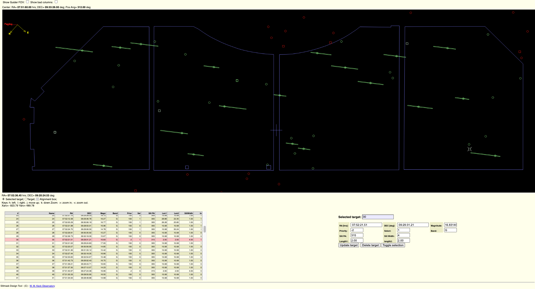
The canvas window is interactive and can be rotated or panned with the mouse. Zooming in an out can also be accomplished with the < and > keys. Remember to update your parameters every time you recenter in order to save the new RA and DEC positions.
Procedure
Quick summary of basic mask design
- Launch the software: python app.py
- Update the parameters
- Click the auto-select button to select targets
- Recenter the targets in the FOV
- Update the parameters to save the new center RA and DEC
- Select alignment boxes and guides stars in addition to the selected targets.
- Generate Slits
- Save the Mask Design File
Details
Make sure that alignment stars and at least one suitable guide star are selected!
By default, slits are lengthened to where they nearly touch each other (the slit separation is a parameter, for which 0.5 arcsec is currently recommended). In cases where overlap would occur, by default the slits are shortened to avoid overlap. In the plots, both the object (drawn to show the requested slit length) and the slit appear, so it is immediately apparent whether slits have been lengthened or truncated.
The final step is to save the mask design, at which point the MDF FITS file is generated, as well as the output text file and the png file. Note the output text file can be used as an input in SMDT or DSIMULATOR.
The first object in the .out file is recognized as the field center if it has a field "PA=nnn" in place of magnitude. Note that this line is also properly formated for the Keck starlist, provided the colons are replaced with spaces.
Mask submission
After designing your slitmasks, you can submit them for milling.Send questions or comments to:DEIMOS Support