Director’s Introduction
Taft Armandroff, Director, WMKO
 Keck Observatory values reaching out to our scientific
community semi-annually via this Observers’ Newsletter.
This issue of the Newsletter is timed to coincide with the
preparation process for observing proposals for the 2011B
semester.
Keck Observatory values reaching out to our scientific
community semi-annually via this Observers’ Newsletter.
This issue of the Newsletter is timed to coincide with the
preparation process for observing proposals for the 2011B
semester.
This Newsletter highlights a number of important developments that observers can factor into their current and future plans for Keck observing. The lead article describes the replacement of the CCDs on the red side of LRIS with new, fully-functional devices that retain the very high quantum efficiency at far-red wavelengths of the CCDs they replace. This red-sensitivity advantage of LRIS has resulted in numerous successful observing programs that would have been marginal or impossible with the original LRIS-R detectors. Two other articles describe important advances with the programs to implement laser-guide-star adaptive optics on Keck I and to deliver a groundbreaking new infrared multi-object spectrograph, MOSFIRE, respectively. Note also the article calling attention to the M-band capability of NIRSPEC coupled with adaptive optics contributed by longtime Keck observer Geoff Blake and colleagues.
Keck Observatory received notification in January that the National Optical Astronomy Observatory’s Telescope System Instrumentation Program (TSIP) has awarded further development funding to the Keck Cosmic Web Imager (KCWI). KCWI is an integral-field spectrograph optimized for precision, sky-limited spectroscopy of low-surface-brightness phenomena. KCWI will feature high throughput, and flexibility in field of view, spatial sampling, bandpass, and spectral resolution. KCWI will cover the optical spectral regime using optimized blue and red channels in a manner similar to LRIS. The preliminary design phase and the beginning of the detailed design phase of KCWI were previously funded by TSIP as a result of the 2009 solicitation. This new award for $1.23 million will fund the completion of detailed design and several long-lead-time hardware items. The KCWI Team is led by P.I. Chris Martin and Project Manager Anna Moore, both of Caltech. ✶
LRIS Gets a New Red Dewar and Detectors
Marc Kassis, Support Astronomer, WMKO
Thanks to heroic efforts by the staff at UCO/Lick Observatory, LRIS enters 2011 with a new red CCD dewar that restores all of the important benefits initially delivered by the LRIS Red II system we commissioned in mid-2009, even exceeding that dewar's detectors in far-red throughput. In December 2010, WMKO and UCO/Lick installed and commissioned the so-called “LRIS Red III” dewar, consisting of two 2K×4K LBNL high-resistivity CCDs in a dewar modified to safeguard the array from the thermal stresses that caused charge-transfer-efficiency (CTE) problems in the previous mosaic. The new system once again covers the entire LRIS field of view with fully functional detectors to support both imaging and multislit observations. Zero points and spectroscopic throughput measurements indicate that the new CCDs meet or exceed the sensitivity of the LRIS Red II mosaic, and although they are not free of cosmetic defects, the arrays are flatter than their predecessors.
|
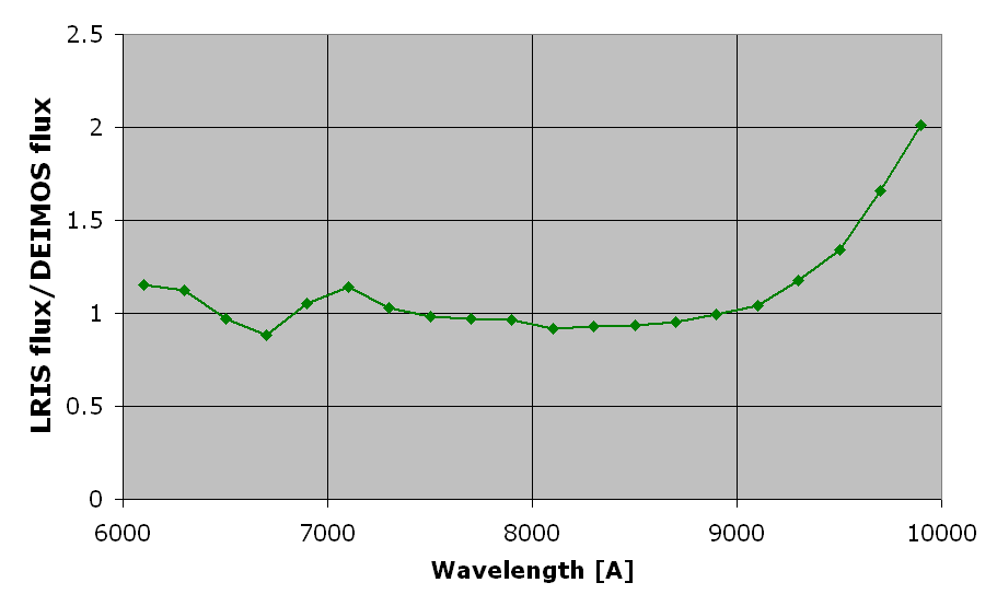
| Figure 1. Relative throughput of LRIS and DEIMOS from 6,000–10,000 Å using their respective 830-line gratings (this comparison gives DEIMOS a slight advantage because its 830/8640 grating is gold-coated and thus offers higher throughput than the aluminum-coated LRIS 831/8200 grating). The two instruments are competitive at wavelengths below 9000 Å, but LRIS outperforms DEIMOS at redder wavelengths. |
Engineering data acquired in Dec 2010 were used to characterize the LRIS Red III mosaic’s performance and the results have been posted to the Release Notes now available from the LRIS web pages. Photometric zero points in the I and V bands were calculated to be 27.80 and 27.86, respectively, representing an improvement of 0.5 magnitudes in both bands over LRIS Red I. Brad Holden and Jason Prochaska of UCO/Lick kindly reduced observations of spectroscopic standard stars (see the LRIS Throughput web docs) and established that the LRIS Red III CCDs perform comparably to the LRIS Red II detectors near 1 μm.
In comparison to the LRIS Red I system, LRIS Red III offers several important advantages:
- higher quantum efficiency in the red, extending the useful range of the red side into the reddest optical wavelengths near 1 μm;
- elimination of interference fringes and the associated flat-fielding difficulties resulting from flexure-induced image motion;
- larger detector area for greater spectral range;
- flatter focal plane for more uniform focus across the red field of view.
Cosmetically, the LRIS Red III mosaic appears much flatter than the preceding arrays on LRIS. However, the new detectors also have certain defects of which observers should be aware, including:
- hot pixels and charge traps that should be avoided, including some with tails that extend out to the edge of the array;
- regions where the channel stops have partially failed, leading to columns that have slightly increased signal leaked from neighbors;
- glue voids that require special attention when extracting spectra from these regions.
Observers should be also aware of certain other features associated with the LRIS Red III detectors:
- Increased read noise: one of the detectors in the mosaic is sensitive to temperature and, as a result, both CCDs are operated at the relatively warm temperature of -100°C (relative to -140°C for the LRIS Red II system). Although the warmer operating temperature improves the QE relative to the LRIS Red II mosaic near 1 μm, the elevated operating temperature increases overall read noise from 3 to 4.6 e–.
- Slower readout speed: readout times for full-frame exposures are now 2 min, compared to 1.5 min for the LRIS Red II mosaic.
- Non-linearity: unlike the previous detectors (which were linear up to the ADC limit) the new mosaic’s linear range is now limited to 38,000 ADU.
The LRIS Red III dewar project was “fast tracked” to the telescope after the CTE problem in the LRIS Red II worsened to the point that it impacted all LRIS red science observations. Although the new LRIS Red III mosaic does exhibit a minor amount of CTE loss (smearing 0.67% of the charge) it is far less of a problem than with the LRIS Red II mosaic (which smeared 10%–40% of the charge, depending on the amplifier) and we do not expect this smearing to be detectable in science observations. Modifications to the dewar and detector mount design were implemented in LRIS Red III to prevent the mosaic from reaching what we now realize are temperatures potentially harmful to the LBNL CCDs. We expect no further degradation, but will continue to monitor the system’s performance.
We thank Bob Kibrick, Connie Rockosi, Richard Stover, and the staff of UCO/Lick Observatory for their highly successful efforts to build the new LRIS Red III dewar on a very tight schedule. ✶
Keck I LGS-AO Adopts Free-Space Transport System
Randy Campbell, Support Astronomer, WMKO
Thomas Stalcup, AO/Optics Engineer, WMKO
The laser guide star (LGS) system on Keck I has been redesigned to employ a free-space transport (FST) system to replace the fiber-based transport system that was originally conceived and tested. As reported in the Winter 2010 edition of this newsletter, the fiber is fundamentally incapable of transmitting the high-energy (up to 3.5×10⁻⁷ Joules) laser pulses to the launch telescope. Thus, our team is developing a series of mirrors plus a redesigned Beam Transfer Optical Bench (BTOB) in order to deliver the maximum power generated by the Lockheed Martin Coherent Technologies (LMCT) laser to the mesospheric sodium layer at 90 km altitude.
The optical elements in the beam train from the laser to the BTOB are flat mirrors with the relatively simple purpose of relaying the laser output beam to the launch optics. All laser light will be contained in laser-safe, light-tight tubing between mirrors, each of which will also be safely enclosed. The FST system must account for differential motion between the telescope and the laser as a function of elevation change. This is complicated by the fact that HIRES occupies nearly the entire Nasmyth platform on Keck I and so the FST system does not have access to the elevation axis of the telescope. Because of this, a relatively complicated off-axis tracking system is required. The Elevation Tracking Assembly (ETA) consists of a structure on top of the laser and HIRES enclosures, as well as an assembly mounted to the telescope elevation ring (see Figure 2). It performs the task of transferring the laser beam from the Nasmyth platform to the portion of the telescope that moves in elevation. It does this with two single-axis rotation stages. Placing both of these stages in a common plane that is perpendicular to the telescope elevation axis eliminates the need for more complicated two-axis tracking devices.

|
| Figure 2. Free-space transport (FST) truss structure being installed on top the laser and HIRES enclosures. The truss will support some of the FST relay mirrors and beam containment tubing. The Keck I elevation ring is in the background. |
In addition to elevation tracking control, the FST system will actively align the laser beam by employing a position sensor at the BTOB top end to control a steering mirror at the laser table on the Nasmyth platform below. This will not only ensure proper beam train alignment but will also have sufficient bandwidth to handle vibration as well. Additionally, an “Up Tip Tilt” (UTT) mirror on the BTOB will handle both atmospheric tip/tilt correction and beam steering on-sky to keep the artificial guide star stable on the wavefront sensor. So, although the optical design of the FST is relatively simple, the dynamic beam control requirement does present significant challenges.
The FST design passed a detailed design review in early December and the team is now installing the hardware on the Keck I telescope. Second light (first light was with the fiber in Jan 2010) should occur in March 2011. Once the FST system is in place (expected spring 2011), it will be integrated with the rest of the Keck I Adaptive Optics (AO) system, allowing closed LGS-AO loop testing to occur in late spring 2011. The Keck I laser commissioning will continue throughout semester 2011A and into 2011B.
After the Keck I LGS-AO system is fully operational, the OSIRIS spectrograph will be moved from Keck II to a permanent mount in the Keck I AO enclosure during January through March of 2012. OSIRIS will be available for science on Keck II through December of 2011. We anticipate it being available for shared risk science on Keck I beginning in April of 2012. Observers should understand that OSIRIS will likely be unavailable from January through March 2012. ✶
New NIRC2 Dithering Scripts May Improve Your “MPG”
Marc Kassis, Support Astronomer, WMKO
In December 2010, we released for observer use modified NIRC2 data acquisition and dithering scripts. The new scripts improve the on-sky observing efficiency in both NGS and LGS-AO observing modes by reducing the number of delays due to status checks and time lost waiting for data writing to complete. Minor modifications were made to the display software quicklook to handle more rapid image exposures with times as short as five milliseconds. Because the detector server is more prone to crash with the new scripts (roughly once per night), the new software is deployed only with consent from the observing team.
Nighttime engineering image acquisition timing tests using simple goi commands and a bxy3 three-point dither pattern demonstrate that a little more than eight seconds are saved per dither position. The time saved is primarily due to code modifications that perform telescope moves in parallel with writing data to disk, accounting for five seconds per image. The total time saved for a three-point dither pattern was measured to be 25 seconds on average.
Observers who will benefit the most from the updated scripts are those with observing programs requiring many dithers. As an example, long exposures of 300 s with a five-point dither pattern executed four times require approximately two hours to complete. For this program, the observers would save approximately 15 min per night. At the other extreme, short exposures of 30 s with a five-point dither pattern per object observed in JHK filters require 30 min to complete. For 20 objects a night observed in this mode, the new scripts would save 45 min per night.
Scripts that have been modified include goi, test, lg_dither, xy, wfg, and wfao. The software modifications are designed to be backward compatible with any existing custom observing scripts that use these commands, and will automatically take advantage of the higher efficiency. However, observers who employ a modified version of lg_dither (and you know who you are!) should consider upgrading their code. Your Support Astronomer will be happy to provide assistance in converting user scripts to use the new code.
Although the scripts improve observing efficiency, we are still experiencing some detector server crashes as we discover new and exotic bugs never before seen during NIRC2 observing. Many of the bugs were discovered during 2010B science nights when observers agreed to use the new scripts, and we greatly appreciate their willingness to test new software. To reduce the server crash recovery time to about three minutes, we have developed routines to restart the detector server, restore observing parameters, and restart observing software. Once the current stability issues are addressed, we will release the new software for regular nighttime use. Please consult your Support Astronomer if you are interested in using the new, high-efficiency scripts for your NIRC2 observing run. ✶
First Results from NIRSPEC-AO in the Thermal IR
G. A. Blake, K. M. Pontoppidan, C. Salyk, Caltech
Because NIRSPEC’s AO pupil stop was originally installed in the same filter wheel as its KL- and M-wide filters, it’s never before been possible to observe with these thermal IR filters in AO mode. Fortunately, a second AO pupil stop was installed in filter wheel 2 during the NIRSPEC service mission in September 2009, allowing these “thermal IR” filters to be used in AO mode for the first time. On the nights of 13–15 December 2010 (UT) we carried out an extensive program of M-band NIRSPEC-AO observations of the CO Δv=1 rovibrational emission from the disks encircling pre-main sequence stars. A smaller suite of disks was also studied in the L-band window to search for water and the organic species HCN and C2H2.
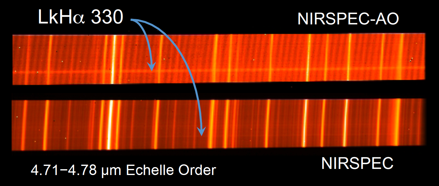
Although the raw counts rate drops by a factor of about ten compared to natural-seeing-limited NIRSPEC data, and even with some 15 warm mirrors plus a dichroic between the instrument and sky, the M-band source/sky emission-line contrast is markedly improved in NIRSPEC-AO mode thanks to the cold pupil stop and smaller solid angle of sky imaged by each pixel. Figure 3 shows the “A” nod position data for the transitional disk LkHα 330 in both modes. Importantly, the drop in background is sufficient to enable multiple reads of the detector, which substantially offsets the drop in throughput. The longer integration times also drop the number of coadds, which lowers the fixed pattern (read) noise. Nodding along the slit is quite accurate (to within 1-2 pixels once the loops are closed), and over the course of three nights with seeing variations from 0.5 to >2 arcsec the Strehl ratio remained remarkably consistent. Drifts perpendicular to the slit, hinted at in natural-seeing NIRSPEC observations, and a ~5–6 pixel offset along the slit between SCAM and the spectrometer chip (toward the A nod position) were accurately diagnosed, and are being assessed by the Keck Observatory staff. Neither precluded the acquisition of science-quality data.
|
| Figure 3. Comparison of NIRSPEC M-band spectra acquired in AO mode (top) non-AO mode (bottom) of LkHα 330, a pre-main sequence star+disk system in the Perseus molecular cloud. The accentuated fringing in the AO-mode data results from the slow f-number of the beam. Note the marked improvement in visibility of the source in the AO-mode data. |
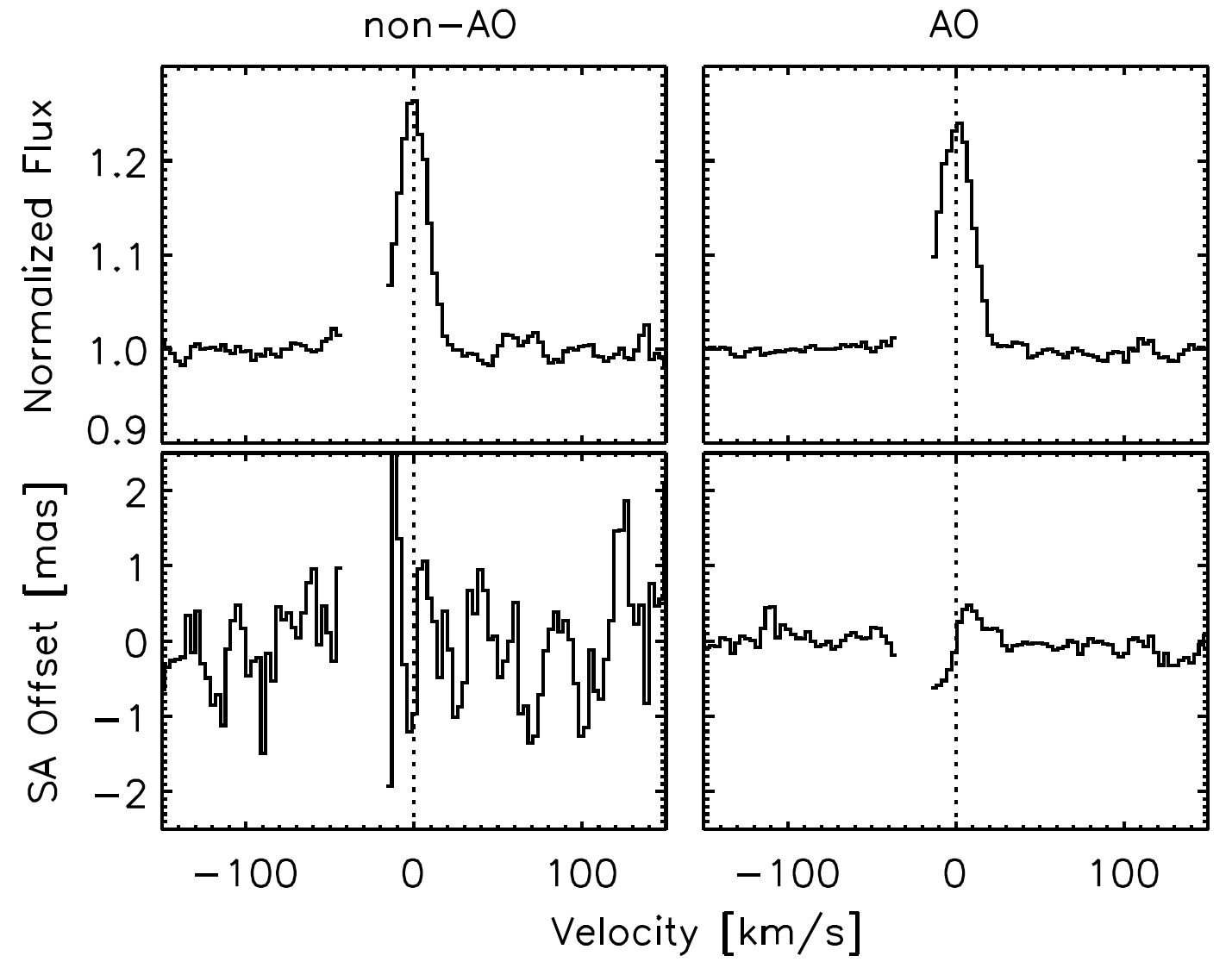
To generate spectra, curvature in the 2-D echellograms is first removed and an accurate wavelength scale derived from the numerous sky lines (see Salyk et al. 2009 for a full description of the data reduction). In addition to extracting 1-D spectra, we also now produce Spectro-Astrometry (SA) signatures by measuring the centroid of the emission versus wavelength. Such M-band SA data were first acquired for disks using CRIRES at the VLT (Pontoppidan et al. 2008), and represent a significant new capability for NIRSPEC M-band observations. A comparison of the spectra and SA signatures acquired in NIRSPEC-AO (14 December 2010, 19 min of integration) and NIRSPEC (17 December 2010, 18 min of integration) modes at comparable airmasses and natural seeing of <0.7” are shown in Figure 4.
|
| Figure 4. Comparison of CO M-band spectra from the transitional disk LkHα 330 (top) along with the Spectro-Astrometric (SA) signature in natural seeing (left) and NGS mode (right). Seven CO lines are stacked to produce the spectra (Salyk et al. 2009), and regions with <70% atmospheric transmission are masked. To process the SA data (see Pontoppidan et al. 2008 for a detailed description of SA observing procedures and data analysis), spectra were acquired at slit position angles of 165° and 345°. The Keplerian signature from gas in the inner regions of the disk is clearly detected in the AO observations. |
To remove atmospheric and instrumental artifacts, SA signatures are best obtained by paired spectra with a selected slit position angle (PA) and PA ±180°. In natural-seeing, constant-PA mode, the NIRSPEC image rotator is found to introduce significant and time-variable background at M band that precludes SA observations for all but a select range of PAs. The AO image rotator showed no such structure over the three nights.
From the data presented in Fig. 4, we measure a dynamic range on the continuum (for velocity windows of ±40–150 km s-1) of 188 in the AO-mode, and 121 for non-AO mode observations. Over the same velocity range, the standard deviation for the SA signal is 140 μas for AO observations vs. 760 μas for the non-AO data. Thus, for point sources the sensitivity improves with NGS NIRSPEC-AO M-band observations. Differential refraction corrections are accurately applied, and AO observations can thus be carried out to significant airmasses. At L-band, a first analysis showed about a factor of 1.8 drop in dynamic range on the continuum, but the AO data are not yet optimally processed. The sensitivity difference is likely considerably less, and the instrument response function is much more stable. Thus, echelle-mode thermal-IR NIRSPEC-AO observations are now feasible for a wide range of astrophysical sources, and in cases where high dynamic range is required (disk spectroscopy and SA, transit and/or secondary eclipse observations of extrasolar planets, radial velocity measurements of low mass stars/brown dwarfs) are likely to be superior to natural-seeing-limited NIRSPEC data. Provided the LGS AO corrections are of similar quality, L- and M-band NIRSPEC-AO observations of faint/embedded targets should also yield spectra and SA signatures of high quality. ✶
References
- Spectro-astrometric Imaging of Molecular Gas within Protoplanetary Disk Gaps. K. M. Pontoppidan, G. A. Blake, E. F. van Dishoeck, A. Smette, M. I. Ireland, & J. Brown. 2008, ApJ, 684, 1323
- High Resolution 5 μm Spectroscopy of Transitional Disks. C. Salyk, G. A. Blake, A. C. A. Boogert, & J. M. Brown. 2009, ApJ, 699, 330
The Imminent Arrival of MOSFIRE, Keck’s New Infrared, Multi-Object, Imaging Spectrograph
Bob Goodrich, Observing Support Manager, WMKO
Sean Adkins, Instrument Program Manager, WMKO
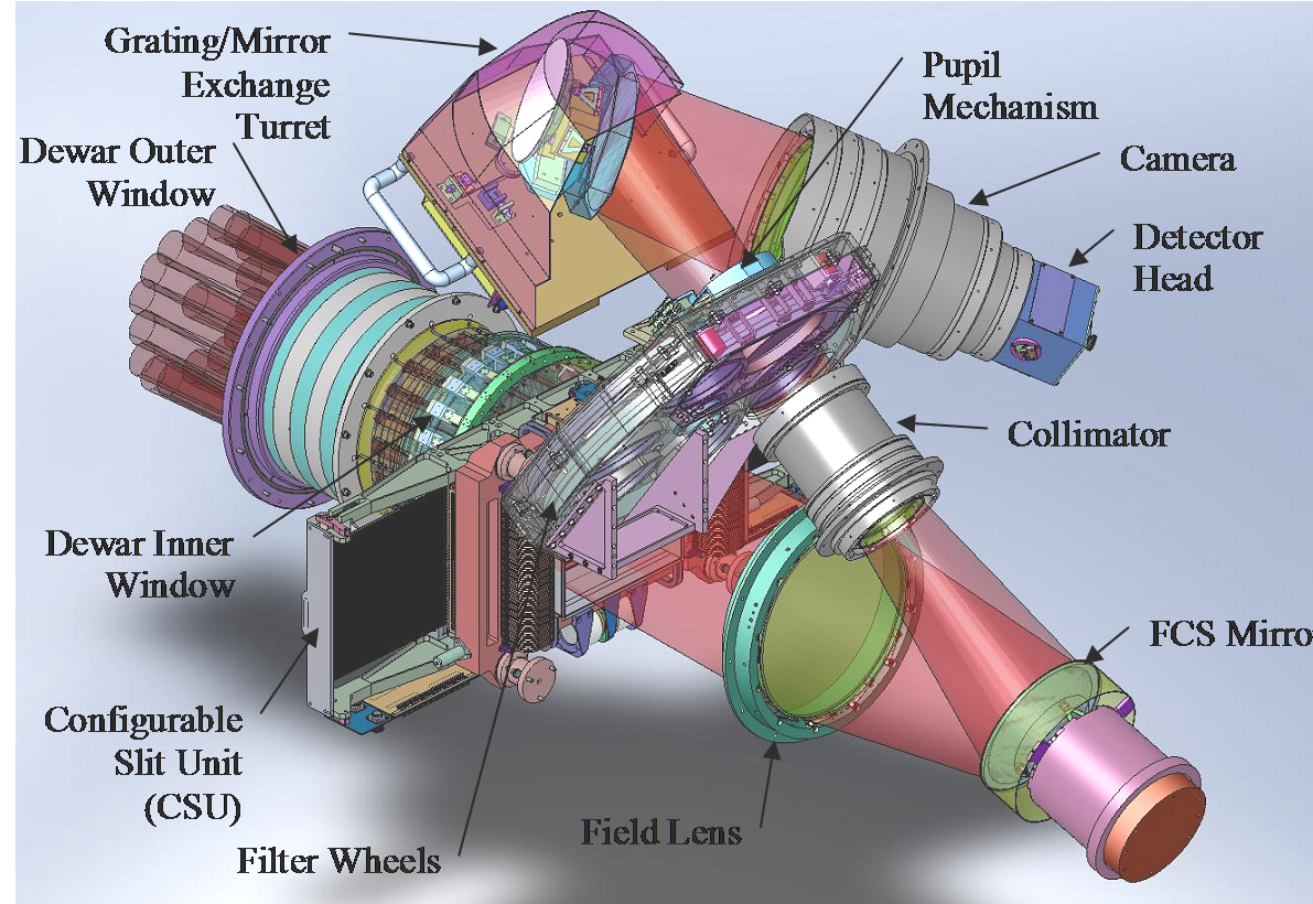
We here at WMKO are anxiously anticipating the delivery of MOSFIRE, the latest addition to our instrument suite. MOSFIRE is a unique, fully-cryogenic, multi-object spectrometer and imager for the Cassegrain focus of the Keck I telescope. A refractive optical design provides near‑IR (0.97–2.45µm) multi-object spectroscopy over a 6.14' x 6.14' field of view with a resolving power of R~3,270 for a 0.7" slit width (2.9 pixels in the dispersion direction), or imaging over a field of view of 6.8' diameter with 0.18" per pixel sampling. A single diffraction grating can be set at either of two fixed angles, and order-sorting filters provide spectra that cover the K, H, J or Y bands by selecting 3rd, 4th, 5th or 6th order, respectively. A folding flat following the field lens is equipped with piezoelectric transducers to provide tip/tilt control for flexure compensation at the 0.1 pixel level. The internal opto-mechanical configuration of MOSFIRE is diagrammed in Figure 5.
|
| Figure 5. MOSFIRE’s internal opto-mechanical layout. All components in the optical path, including the CSU, are shown. |
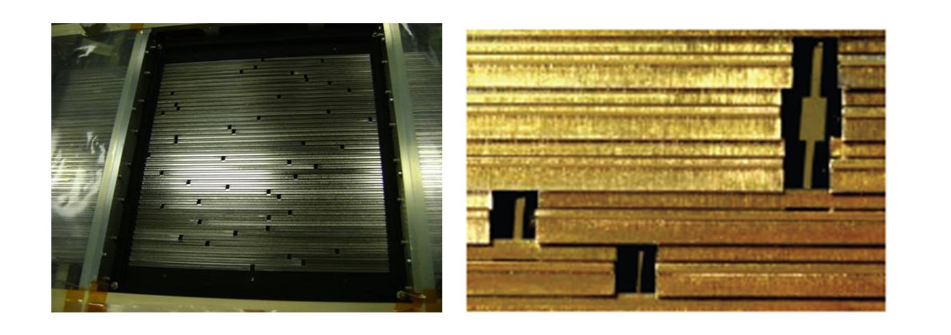
A special feature of MOSFIRE is that its multiplex advantage of up to 46 slits is achieved using a cryogenic Configurable Slit Unit (CSU) developed in collaboration with the Swiss Centre for Electronics and Microtechnology (CSEM). The CSU is reconfigurable under remote control in less than 5 minutes without any thermal cycling of the instrument. Slits are formed by moving opposable bars from both sides of the focal plane. An individual slit has a length of 7.1" but bar positions can be aligned to make longer slits. Figure 6 shows the CSU configured with a typical multi-slit mask (left side of the figure) and a close up of three slits (right side of the figure). When the CSU masking bars are removed to their full extent and the grating is changed to a mirror, MOSFIRE becomes a wide-field imager. Using a single, ASIC-driven, 2K×2K H-2RG HgCdTe array from Teledyne Imaging Sensors with exceptionally low dark current and low noise, MOSFIRE will be extremely sensitive and ideal for a wide range of science applications. A recent SPIE paper (McLean et al., 2010, SPIE Proceedings Vol. 7735) describes the instrument in greater detail.
|
| Figure 6. Left: a picture of the CSU showing a mask configuration. Right: a close-up showing the black knife-edge slits. |
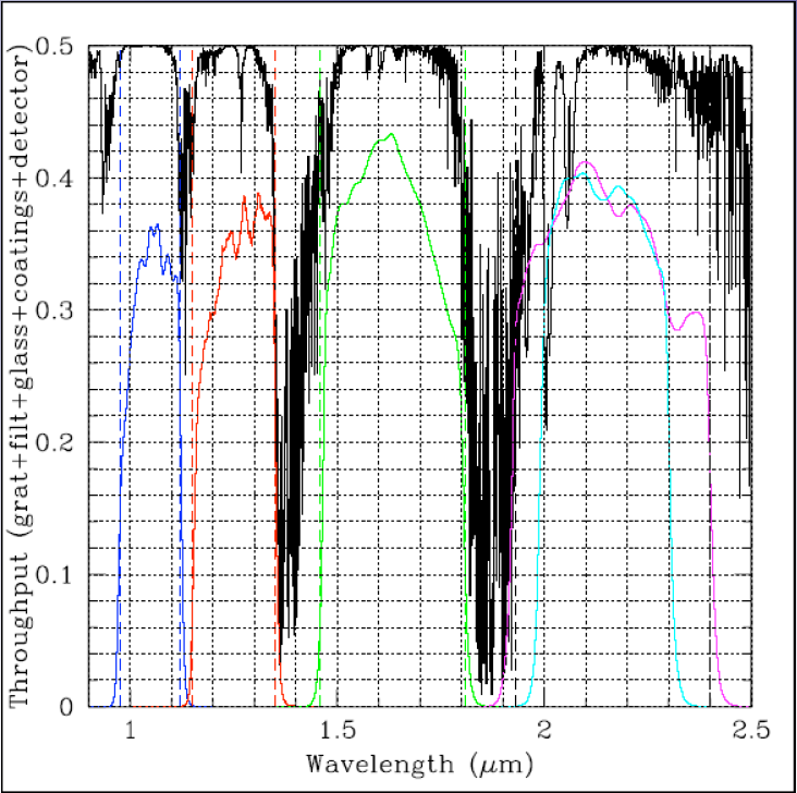
While the observatory has been preparing for MOSFIRE — adding power connections, new glycol and cryo lines, CCR compressor, local controls, etc. — the integration and test process for MOSFIRE has been underway in a clean room facility at Caltech. Members of the project team from UCLA, Caltech, and WMKO have been working together to test MOSFIRE and to address the technical challenges that can be expected in an instrument of this complexity. MOSFIRE has completed 8 cool downs and has demonstrated excellent image quality. The throughput based on as-built measurements for all of the science optics including the grating and filters, and including the detector QE, is shown in Figure 7. It meets or exceeds the requirements in all bands and the average throughput over the full bandwidth in each band is > 30%.
|
| Figure 7. MOSFIRE’s throughput in Y, J, H, Ks and K (blue, red, green, cyan, and magenta curves, respectively) plotted along with the atmospheric windows. |
The instrument’s flexure correction system has also demonstrated excellent performance, and the final cool down (number 9) is planned for March 2011. The MOSFIRE pre-ship review is planned for April 11, and the first on-sky commissioning night is expected to be May 20. Commissioning will continue through the rest of semester 2011A, and throughout 2011B. We, along with many observers, are looking forward to MOSFIRE entering regular operations.
This material is based upon work supported by AURA through the National Science Foundation under AURA Cooperative Agreement AST 0132798, as amended. Funding for MOSFIRE has also been provided through a generous donation by Gordon and Betty Moore. ✶
New Computer Speeds OSIRIS Reductions
Jim Lyke, Support Astronomer, WMKO
For OSIRIS users, the wait for the data reduction pipeline (DRP) to convert their 2D raw spectra into a 3D reduced data cube seemed like forever. While the wait was actually 60-70 s, those minutes added up over the course of the night. We now have a new DRP machine in service for OSIRIS which reduces raw data into data cubes in 30-40 s — even faster than your laptop! We are considering additional upgrades to speed the reductions even further. For your next observing run, make sure you ask your Support Astronomer to use the new DRP machine. ✶
SpecPro Tool Enables Interactive Analysis of DEIMOS Spectra
Dan Masters, Graduate Student, UC Riverside/Caltech (visiting)
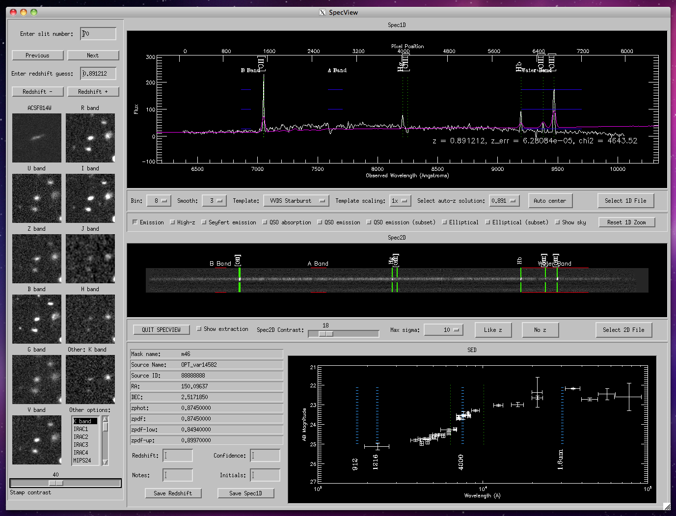
SpecPro is an interactive IDL program we developed to help with our analysis of DEIMOS spectra of galaxies in the COSMOS survey field. The interface (shown in Figure 8) provides a comprehensive picture of a spectroscopic target by displaying the 1D and 2D spectrum as well as available multiwavelength stamp images and overall source SED. Even without multiwavelength survey data, SpecPro is a useful tool for viewing spectra and rapidly finding redshifts. While originally written specifically for DEIMOS, we have since generalized the program so that it can be used to view data from any instrument.
|
| Figure 8. The SpecPro interface displaying a star-forming galaxy at redshift z=0.89. Stamp images of the source are displayed on the left side of the interface, and the 1D spectrum is displayed in the upper right window. On the 1D plot, vertical lines mark the positions of prominent emission features, and a spectral template is overlaid in blue. Under the 1D spectrum is the 2D spectrum, binned to fit the display. Emission lines ([O II], Hβ, Hγ, [O III]) are easily visible in the binned 2D image. The window on the bottom right shows the SED of the source from the ultraviolet to the mid-infrared. The observed-frame positions of important photometric breaks are indicated with vertical dashed lines. |
The interface adapts routines from the DEIMOS DEEP2 pipeline for rapid redshift determination by automated cross-correlation against a variety of galaxy spectral templates. It also allows the user to overlay common emission and absorption lines on both the 1D and 2D spectrum, change the redshift manually, bin, smooth and zoom on the 1D spectrum, automatically re-extract 1D spectra from 2D, save results to file from within the interface, and overlay the slit on the stamp images, among other capabilities.
We have found the program to be very useful in working with our spectroscopic sample, and we think others in the Keck community may benefit from it as well. The program is publicly available at http://specpro.caltech.edu. ✶
Our New Paradigm: All VNC, All the Time
Gregory D. Wirth, Support Astronomer, WMKO
Jim Lyke, Support Astronomer, WMKO
Robert W. Goodrich, Observing Support Manager, WMKO
As part of an initiative to streamline instrument operations, WMKO has recently implemented a new observing mode we call “All VNC All the Time.” In addition to simplifying the way we run instrument software, this mode offers some important benefits for observers and support personnel alike.
In the past, Waimea-based observers would bring their instrument and telescope software up in one of two ways, depending on whether remote collaborators would be joining in. Observers without remote collaborators would run the software in the native X-windows environment; however, observers using mainland-observing mode would run their software within a set of Virtual Network Computing (VNC) desktops, thus permitting their windows to be shared with colleagues at another site.
As observers and WMKO staff became more comfortable with operating the instrument control GUIs under VNC, we realized that doing so offered a number of important benefits:
- More robust: Since the VNC sessions run within a virtual server, the instrument GUIs will persist even if the observer disconnects from the server. This allows the instrument software to keep running even if the observer’s computer experiences a problem. When the observer reconnects to the server, the VNC session is recovered and observing can resume uninterrupted.
- Better eavesdropping: When the instrument software is run under VNC, the Observing Assistants at the summit can bring up a copy of the software in “read-only mode” and eavesdrop on the observing session, thereby becoming more knowledgeable about the operation of our instruments.
- Better troubleshooting: If instrument problems occur at night, the Support Astronomers can easily bring up a copy of the observer’s screens from home, speeding the recovery from problems.

|
| Figure 9. The main screen on kvncgui, our new tool for launching instrument VNC viewers. Simply enter the VNC password and click Launch Viewers! |
Given all of the above benefits, we have now eliminated this distinction and made VNC mode the default mode of operation for all of our instruments. The various instrument startup checklists have now been updated to instruct observers to launching their VNC viewers, a step which is trivially accomplished via our special GUI (see Figure 9) that lets you fire them all up with one click. Your Support Astronomer will be glad to assist you with VNC startup. Please check it out the next time you observe from Waimea and let us know your impressions. ✶
A Better Way to Submit Mainland Observing Requests
Gregory D. Wirth, Support Astronomer, WMKO
Jeff Mader, Software Engineer, WMKO
Observers who want to request remote observing for their Keck run can now do so more conveniently via our new web form, saving both you and the observatory time. Until recently, we handled all requests strictly via email. This approach worked well when the volume of requests was low, but with remote observing now employed on over 40% of our observing nights, the number of requests has become more difficult to track. Thus, we've decided to implement a real tracking system which provides a web interface for submitting your requests (see Figure 10) and a database for storing them.

|
| Figure 10. Our new web form makes requesting mainland observing a snap. |
You can access the new form by logging into your WMKO Observer Home Page, which displays a list of your upcoming Keck runs. Click the link reading Request Mainland Observing to bring up the form. Just fill in the blanks and click Submit and your request is on its way to us. You should receive a response within 3 business days. We hope the new system will allow us to handle your requests with greater speed, efficiency, and robustness. Please feel free to try it out yourself the next time you make a mainland observing request and let us know what you think! ✶
New Mainland Observing Sites Expand Keck’s Dominion
Gregory D. Wirth, Support Astronomer, WMKO
Robert I. Kibrick, Research Astronomer, UCO/Lick Observatory
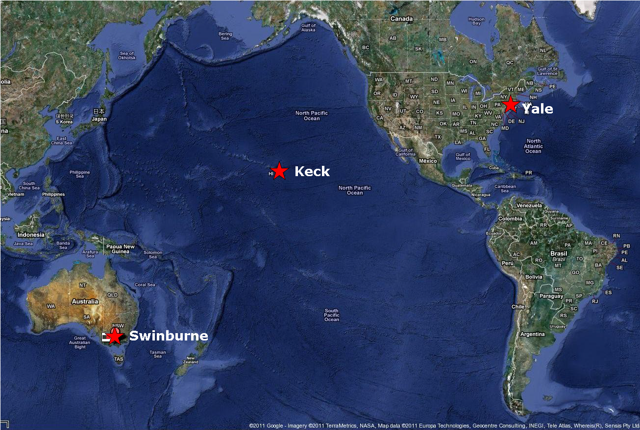
California-based observers have long been making use of the remote observing facilities available at CIT and various UC campuses. Within the last year, two new sites have joined Keck’s “mainland observing” system to expand our footprint well beyond the Golden State, enabling remote observing as an option for astronomers on the east coast of the U.S. and in Australia.

|
| Figure 11. Existing mainland observing sites in California include Caltech and all UC campuses with astronomy departments. |
The east-coast site is hosted at Yale University and is just coming online now in early 2011. The Yale remote observing facility will support all modes, including mainland-only operation (with no Hawaii observers required) and will consider observing requests from Keck observers not associated with Yale, including teams receiving Keck time through NASA.
|
| Figure 12. New mainland observing sites outside of California include Yale U. in Connecticut and Swinburne U. in Melbourne, Australia. |
The Australian site is hosted at Swinburne University in Melbourne and came on-line early in 2010. Although the site does not (yet) support “mainland-only” operation, it has been used frequently by observers eavesdropping on observing runs led by observers in Waimea.
We extend a warm welcome to our colleagues at Swinburne and Yale as they join our mainland observing family! ✶
“Aloha” and “A Hui Hou” to Staff
Robert W. Goodrich, Observing Support Manager, WMKO
The staff of an observatory, as at any organization, are always in a state of flux. People come and go, change their roles, etc. There have been a number of recent personnel changes at WMKO that observers may notice.
 Within the group of Support Astronomers, Grant Hill has
changed roles, and is now the Summit Site Supervisor. In
his new role as the lead of the summit day crew, Grant
will continue to make great use of his SA background,
being able to translate observing needs to the technicians
and engineers that keep the telescopes and instruments
properly configured and running. While observers will miss
him in his observing support role, he will bring strong
scientific knowledge and judgment to the daytime
operations.
Within the group of Support Astronomers, Grant Hill has
changed roles, and is now the Summit Site Supervisor. In
his new role as the lead of the summit day crew, Grant
will continue to make great use of his SA background,
being able to translate observing needs to the technicians
and engineers that keep the telescopes and instruments
properly configured and running. While observers will miss
him in his observing support role, he will bring strong
scientific knowledge and judgment to the daytime
operations.
 Another Support Astronomer, Al Conrad, has also moved on
after many years of service to the Observatory. Al is
taking on the new challenge as the AO Systems Engineer for
LINC/NIRVANA, a
major interferometric instrument for the Large Binocular
Telescope (LBT). Al’s operational and
development experience at Keck should provide an excellent
base of expertise for the LINC/NIRVANA development team,
based in Heidelberg, Germany.
Another Support Astronomer, Al Conrad, has also moved on
after many years of service to the Observatory. Al is
taking on the new challenge as the AO Systems Engineer for
LINC/NIRVANA, a
major interferometric instrument for the Large Binocular
Telescope (LBT). Al’s operational and
development experience at Keck should provide an excellent
base of expertise for the LINC/NIRVANA development team,
based in Heidelberg, Germany.
 Also within Observing Support, we welcome a new Night
Attendant, Rodney Eisenhour. Rodney and the other NAs provide
important safety and technical support at the summit, helping
the OAs, SAs, and engineers to troubleshoot problems, check on
weather, etc. Another very important aspect of the NA job is
spotting aircraft during LGS-AO operations. Rodney comes to us
with some great technical skills and a winning personality,
and we look forward to his contributions to the Keck team.
Also within Observing Support, we welcome a new Night
Attendant, Rodney Eisenhour. Rodney and the other NAs provide
important safety and technical support at the summit, helping
the OAs, SAs, and engineers to troubleshoot problems, check on
weather, etc. Another very important aspect of the NA job is
spotting aircraft during LGS-AO operations. Rodney comes to us
with some great technical skills and a winning personality,
and we look forward to his contributions to the Keck team.
 Those of you with newsworthy science (and isn’t that
all of you?) may also have the opportunity to work with
our new Communications Program Officer, Larry
O’Hanlon. Larry holds a B.A. in Earth Sciences from
UC Santa Cruz and also earned a graduate certificate from
the UCSC Science Communications Program, making him
ideally suited to sharing Keck’s astronomical
discoveries with the public. He has 20 years of
professional experience in science journalism and media
consulting, most recently as a Senior Science
Correspondent for the Discovery Channel’s on-line
Discovery News. We also look forward to
Larry’s contributions to our team, and are sure you
will enjoy working with him. Please feel free to contact
him at his Keck e-mail address, lohanlon@NOSPAMkeck.hawaii.edu.
✶
Those of you with newsworthy science (and isn’t that
all of you?) may also have the opportunity to work with
our new Communications Program Officer, Larry
O’Hanlon. Larry holds a B.A. in Earth Sciences from
UC Santa Cruz and also earned a graduate certificate from
the UCSC Science Communications Program, making him
ideally suited to sharing Keck’s astronomical
discoveries with the public. He has 20 years of
professional experience in science journalism and media
consulting, most recently as a Senior Science
Correspondent for the Discovery Channel’s on-line
Discovery News. We also look forward to
Larry’s contributions to our team, and are sure you
will enjoy working with him. Please feel free to contact
him at his Keck e-mail address, lohanlon@NOSPAMkeck.hawaii.edu.
✶
Back Issues
Please see the Keck Observers’ Newsletter Archive.