 |
||||||||||||||||||||||||||||||||||||||
The procedures for calibrating the LGS AO system are described in this document. The OBS should be rebooted periodically to avoid potential problems with suspended tasks, especially before long LGS AO runs. Instructions on rebooting the OBS can be found here. The following procedure assumes that the OBS has already been rebooted and that the stages have been initialized and that the optical axis has been checked. Note that we have not been rebooting the OBS lately or encountering any problems with the OBS software.
Start the real time LBWFS software:
From the LBWFSCALS widget, do the following:
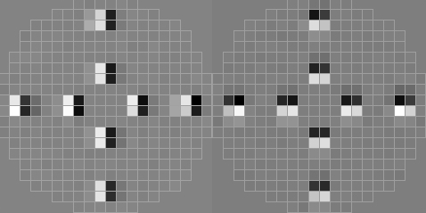
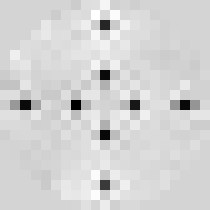
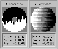
This is the part that could go wrong. Let's assume that is has converged and later we will deal with the case where the algorithm has not converged after 5 minutes or so. Case 1: The algorithm converges After the algorithm has converged, the program will poke a cross pattern, measure the centroids and reconstuct the actuators. If the convergence is good, the centroids and the reconstructed actuators will look something like
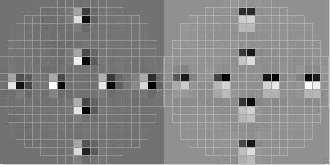
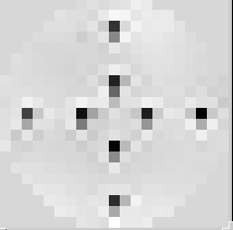
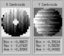
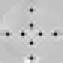
If, on the other hand, the convergence is bad, the centroids and reconstructed actuators could look like
or the actuators could look like they are shifted by one subaperture to the left, right, up or down. You can tell for sure whether this is happening by reading the correlation value printed in the IDL session: it should read a value greater than 0.9. If not, then it hasn't converged properly and you could try running it again or following the instructions for the case when it does not converge. Case 2: The algorithm does not converge If the algorithm does not converge or it converges to the wrong value, you will have to give it a better starting estimate. The golden rules of thumb are:
Move LBS manually such that the DM/LBWFS registration is approximately correct in both x and y. You can check by pressing the CHECK LBWFS REG button. Do not worry at this point if it is one subaperture out. Once it is close, write down the LBS positions for future reference. Now run the DM/LBWFS registration again by pressing DM/LBWFS REG. If it fails the first time, you might want to try it again.
If it still hasn't worked, you will have to do it the ole kine way, the way the early pioneers used to do it. Once the DM/LBWFS registration is complete, define and save the 20x20 LBS named position. Registering the 5x5 lenslet array by poking actuators is difficult. Instead, we will try to register the 5x5 lenslet array to the 20x20 lenslet array by taking advantage of the fact that, when the two lenslet arrays are registered to each other, the spots they produce will have the same x0, y0. The LBWFS calibration tool will adjust the position of the LBS until this is true. Then define and save the 5x5 LBS named position. In the unlikely event that the tool has problems finding the correct 5x5 position, then do the following:
The purpose of this step is to set the DM actuators (hence shape) in a static mode (open loop) so that they correct the non-common path aberrations. There are different ways to do it depending on the instrument. For OSIRIS, NIRSPAO and IF (and also for NIRC2 in an emergency when you don't have time to run the full image sharpening): load a phase map that has normally been created lately and corresponds to the static aberrations in the imaging path. This phase map name depends on the instrument in use. For NIRC2, we run the NIRC2 image sharpening algorithm. Loading the phase map
Repeat Steps 3, 4 and 5 three more times. Judge on Wyko display that that the fringes are reasonably straight (for the case of zeros.ph). If it is not the case, iterate steps 3, 4 and 5. If zeros.ph was selected and you are happy with the fringes, redefine the DM origin file by clicking on click on Save voltages as DM origin . Dismiss DM Control Checking the Wyko phase map: The Wyko interferometer that we use to measure the shape of the DM surface is very sensitive to vibrations. It is necessary to check any phase measurement. Under quiet conditions, the returned phase will look very smooth and does not present any phase discontinuity. Examples of thoses instances are shown on the left in the table below. The user would click on accept button for such cases On the other hand, the returned phase may show the presence of phase discontinuities, and the user would click on redo. If you are having difficulty in making the measurement due to the presence of vibrations, you may ask the summit crew to turn telescope oil off.
If you have problems with the WYKO software (e.g., no phase map is returned), then you may want to check that the software is running. You can VNC onto wykopc or k1wykopc (the password is the same as for the k2ao account) and check that the "WYKO-Vision" program is running. If not you may (re)start the program. If this fails, you can ask someone on the summit to reboot the WYKO PC.
If there is no optimized phase map, we just assume the flat shape is the best one... One can optimize the image quality on KAT by adjusting the focus (SFP z) and loading DM zernikes (from the DM zernike widget) until the best image is found on KAT.
Make sure the DM is flat by loading a zeroes.ph phase map from DM control (see above for instructions). Save voltages as DM origins. Load the best shape using Load voltages from file and selecting the latest OSIRIS calibration file. If this does not yield adequate image quality, move the SFP-z and change the DM Zernikes until the image quality is good. Remember to Define and Save the SFP position (for OPTOSIRIS, OSPEC and OSIMG) and the new DM shape using Save voltages to file.
Once we have the right shape on the DM, click on RECORD IMAGE to take an image. Ensure that all subapertures are evenly illuminated, that 20x20 mode is being used, that the LBS is at the defined position (20x20) and that the saved X0, Y0 values are being used.
Then click on "SAVE AS COG" in the LBWFS Calibration Tool. This will save the cog file for the 20x20 mode and the 5x5 mode.
LGS AO WFS Calibration
To calibrate a second or third instrument, run through all the same steps except:
Once you have completed the calibrations, you can check to see how good they are by running the AO calibrations check procedure.
2. SET ORIGINS TO ZERO This sets the LBWFS cog file to zeros.cog. 3. Select FIXED X0, Y0 If button reads FLOAT X0,Y0, click it so it says FIXED X0,Y0 4. Move LBS Send LBS to the value you had recorded that was approximately correct. 5. RECORD IMAGE
6. CHECK LBWFS REG Press CHECK LBWFS REG and look at the reconstructed actuators.
7. Press SET ORIGINS TO ZERO 8. Define and save the LBS position Write down the values for the LBS position and hit DEFINE and SAVE in the SC GUI LBS screen. 9. Save the X0, Y0 values Write down the X0, Y0 values and save them by hitting the SAVE X0, Y0 VALUES. This will save the X0 and Y0 values. Now you can continue with the calibrations. 9. Determine the 5x5 position Now send the LBS to the 5x5 named position. Take an image and record the x0, y0. Move LBS until the x0, y0 is the same as was calibrated for the 20x20 case. Ensure that there are 5x5 spots on the CCD. Then define and save the 5x5 named position for LBS. For more information, please contact . |