 |
Calibrating the LGS AO system
|
 A0. Notes on this page: A0. Notes on this page:
- X: Indicates steps done once, X can
be N2 for NIRC2, or O for OSIRIS
- XNS:
Indicates steps done once per instrument being
calibrated, X can be N2 or O, NS is NIRSPAO
A1. Bring up the AO tools:
- Log in as "kNobsao", where N can be 1 or 2
- Select kNao VNC Menu -> Check VNC Server Stat and
check that four VNC servers are running. If not, start the
servers (ask for assistance if needed).
- Start the VNC viewers
Off the desktop menu select:
- k2 AO VNC Menu -> Start Image Quality Viewer (left) on
your favorite left display.
- k2 AO VNC Menu -> Start Acquisition Viewer (center) on
your favorite center display.
- k2 AO VNC Menu -> Start LBWFS Real Time Viewer (right) on
the your favorite right display.
- k2 AO VNC Menu -> Start Telnets Viewer on
your favorite display.
- Right-click in the background of the VNC desktop--> LGS AO
Control Menu --> Start LGS Calibrations
After the startup, you should see the following GUIs:
- MAORI
- TT graphs
- The SC GUI (continously check SC GUI for faults (indicated in red))
- The IDL "Calibration tool" titled "Keck I calib" or "Keck II calib"
- The WFS intensity display
- The STRAP intensity display
- The "LBWFS CALS" tool
- Instrument Software:
- K1: Manually run osirisSetupNight on the OSIRIS VNC sessions
- K2: NIRC2 instrument software should come up
automatically
- Manually start Firefox -> WYKO display
A2. Reboot WFC
- MAORI -> Scripts -> Reboot WFC
- A new window will launch to reboot and go away when complete (about 4 minutes)
A3. Restart LBWFS camera server
- NEW: 20190617
-
- Ensure room lights and AO fiber source are off (or at least
SND = BLOCK)
- Open xterm as kNobsao@kNaoserver
- Run "LBWFSCamServer restart" (takes about 1 minute)
- Normally, you no longer have to update the LBWFS camera config
file, but if you must...
To update the LBWFS camera config file:
- As kics@(k1)lbwfs-camera-server
- Edit
/kroot/rel/default/Versions/kss/magiq/camera/webCamServer/default/kNlbwfs.dat
- N.B. BIAS0 = LEFT, BIAS1 = RIGHT
- Enter a daylog with your updates
N2/O
NS
A4. Run the calibration setup: on the Calibration Tools
Gui, select Calibration setup
- Keck 1:
-
- Select OSIRIS
- Select NGS (you will re-do this in LGS mode)
- Set SND to 0.1%, note original value
- Take 1 sec exposure on ACAM
- Verify that SFP is on OPT_AXIS pixel in qfix/acampo.dat
(currently 449.75, 503.40 in 2016)
- Return SND to original value
- Keck 2:
-
When prompted
- Select NIRC2 instrument first
- Select LGS AO
- Select light to "strap/LBWFS"
- Select Sodium Dichroic when prompted
N2/O
NS
A5. Register the DM
- Run DM Control on the Calibration Tool
- Click Clear Voltages on the DM Control GUI
- Review the real time WYKO phase map and verify the
phases are relatively straight.
- Run the DM WLS registration on the
Calibration Tool
- N.B.: If after the "Null Centroids" step the Centroid
averages as reported on the WFS Intensity
Display are greater than 0.02, please type
"FSMOFFLOAD" from the Calibration Tools IDL
prompt.
O
A6. Keck 1 only: Redo Cal Setup in LGS mode
When prompted
- Select OSIRIS instrument first
- Select LGS AO
- Select light to "strap/LBWFS"
- Select Sodium Dichroic when prompted
- Run the DM WLS registration on the Calibration Tool GUI: DM WLS Registration
B1. From the LBWFS Calibration tool gui:
N2/O
NS
B2. Setup for cals
- Select Sodium Dichroic when prompted
- When the idl prompt returns, the process is complete.
B3. Align TSS (First Instrument (i.e., NIRC2) ONLY)
- N.B.: If tip-tilt graphs do not change and operation is "too quick",
check stcngn and stcngain (should be 1.0 (not 0.0))
- Check counts on STRAP and TT Graphs while
this is happening
- Ensure that the counts on STRAP are
approximately balanced once it is finished
- Check the IDL xterm for problems (e.g., FAILED TO ALIGN)
- DEFINE and SAVE optsodstrap position on TSS
- When the idl prompt returns, the process is complete.
B4. DM/LBWFS REG
- Start the registration by clicking the DM/LBWFS Reg button.
This is the part that could go wrong. Let's assume that is has converged and later we will deal with the case where the algorithm has not converged after 5 minutes or so.
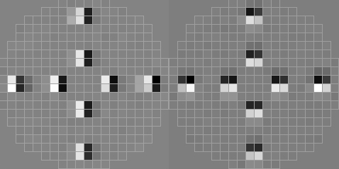
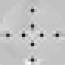
Case 1: The algorithm converges
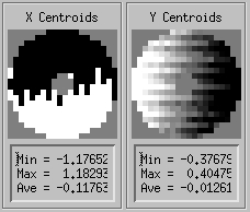
After the algorithm has converged, the program will poke a cross pattern, measure the centroids and reconstuct the actuators. If the convergence is good, the centroids and the reconstructed actuators will look something like
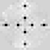
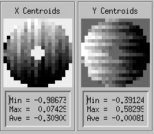
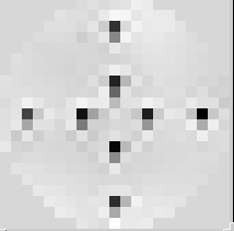
If, on the other hand, the convergence is bad, the centroids and reconstructed actuators could look like
or the actuators could look like they are shifted by one subaperture to the left, right, up or down.
You can tell for sure whether this is happening by reading the correlation value printed in the IDL session: it should read a value greater than 0.9.
If not, then it hasn't converged properly and you could try running it again or following the instructions for the case when it does not converge.
Case 2: The algorithm does not converge
If the algorithm does not converge or it converges to the wrong value, you will have to give it a better starting estimate.
The golden rules of thumb are:
- Each lenslet is 0.4 mm (i.e., you need to move LBS 0.4 mm to move one subaperture)
- Moving LBS in x changes the position of the spots in x
- There are approximately 16.6 pixels per subaperture
- One unbinned pixel is approximately 0.267 arcseconds
Move LBS manually such that the DM/LBWFS registration is approximately correct in both x and y.
You can check by pressing the CHECK LBWFS REG button. Do not worry at this point if it is one subaperture out. Once it is close, write down the LBS positions for future reference.
Now run the DM/LBWFS registration again by pressing DM/LBWFS REG. If it fails the first time, you might want to try it again.
If it still hasn't worked, you will have to do it the ole kine way, the way the early pioneers used to do it. 
- Once the DM/LBWFS registration is complete, define and save the
20x20 LBS named position.
Note: this must be done BEFORE clicking on the "OK" of "please
define and save ... "
B4. Register the 5x5 Lenslet Array
(First Instrument (i.e., NIRC2) ONLY)
Registering the 5x5 lenslet array by poking actuators is difficult. Instead, we will try to register the 5x5 lenslet array to the 20x20 lenslet array by taking advantage of the fact that, when the two lenslet arrays are registered to each other, the spots they produce will have the same x0, y0. The LBWFS calibration tool will adjust the position of the LBS until this is true. Then define and save the 5x5 LBS named position.
In the unlikely event that the tool has problems finding the correct 5x5 position, then do the following:
- Select 5x5 subapertures from the LBWFS calibration tool.
- Select "Float X0, Y0".
- Take an image. Ensure that there are at least 5x5 spots in the image. If not, you will have to find a historical value of LBS where this is true or hunt around manually.
- Ensure that the maximum peak intensity is between 5000 and 10000 counts. Change the integration time if necessary.
- Take an image. Move LBS until the x0, y0 values are the same as those found for the 20x20 case.
- Redefine the 5x5 LBS named position.
In the SC GUI, LB (LBS) change oblbname
= 20x20 and hit S.
| C. Image sharpening (non-common path aberrations)
|
Discussion:
The purpose of this step is to set the DM actuators (hence shape) in a static mode (open loop) so that they correct the non-common path aberrations.
There are different ways to do it depending on the instrument. For OSIRIS, NIRSPAO and IF (and also for NIRC2 in an emergency when you don't have time to run the full image sharpening):
load a phase map that has normally been created lately and corresponds to the static aberrations in the imaging path.
This phase map name depends on the instrument in use. For NIRC2, we run the NIRC2 image sharpening algorithm.
C1. Establish best shape on the DM
N
- Turn off Hepa if needed: Calibration Gui -> Light Source
Control -> Click for Hepa Off to turn the Hepa off.
- Click DM Zernike Control on the Calibration GUI to
bring up the zernike control gui.
- Change the "0 deg atig" to -0.6 . If entered in the
text box remember to press enter.
- Select Image Sharpening. on the Calibration GUI
- Click Auto Image Sharpen
- When completed select Cancel in the WYKO phase map.
- Proceed to section D (LBWFS Calibration)
NOTES:
NIRC2 image sharpening algorithm describes the routine.
This automated process requires
approximately five minutes. After it completes, you may get the
"junk.opd" error message, indicating a wyko problem.
See Twiki troubleshooting page for guidance.
O
- For all other instruments, shape the DM directly as follows:
Loading the phase map
Click on DM control on the WFC IDL widget.
Click on Clear voltages button.
Click on Load phase using WYKO
Select the last saved file for the instrument:
| NIRC2 |
nirc2_yyyymmdd.ph |
| NIRSPAO |
ddmmyy_nirspec_h.ph
|
| IF |
zeros.ph |
| OSIRIS |
zeros.ph |
If you get the "junk.opd" error message, a wyko problem is likely.
See Twiki troubleshooting page for guidance.
|
 |
Check the returned Wyko phase map (see below)
Repeat Steps 3, 4 and 5 three more times.
Judge on Wyko display that that the fringes are reasonably straight (for the case of zeros.ph). If it is not the case,
iterate steps 3, 4 and 5.
If zeros.ph was selected and you are happy with the fringes, redefine the DM origin file by clicking on click on Save voltages as DM origin .
Dismiss DM Control
Checking the Wyko phase map:
The Wyko interferometer that we use to measure the shape of the DM surface is very
sensitive to vibrations. It is necessary to check any phase measurement. Under quiet conditions, the returned phase will look very smooth and does not
present any phase discontinuity. Examples of thoses instances are shown on the left
in the table below. The user would click on accept button for such cases
On the other hand, the returned phase may show the presence of phase discontinuities, and the
user would click on redo. If you are having difficulty in making the measurement due to the
presence of vibrations, you may ask the summit crew to turn telescope oil off.
|
Examples of good returned phase map |
Examples of bad returned phase map |

|

 |
- Problems with the WYKO:
If you have problems with the WYKO software (e.g., no phase map is returned), then you may want to check that the software is running.
You can VNC onto wykopc or k1wykopc (the password is the same as for the k2ao account) and check that the "WYKO-Vision" program is running. If not you may (re)start the program.
If this fails, you can ask someone on the summit to reboot the WYKO PC.
- For IF:
If there is no optimized phase map, we just assume the flat shape is the best one... One can optimize the image quality on KAT by adjusting the focus
(SFP z) and loading DM zernikes (from the DM zernike widget) until the best image is found on KAT.
O
- For OSIRIS:
Make sure the DM is flat by loading a zeroes.ph phase map from DM control (see above for instructions).
VERY IMPORTANT!!!
Define the phase on the DM as the DM origins by clicking
Save voltages as DM origins.
If this does not yield adequate image quality, move the SFP-z and change the DM Zernikes until the image quality is good.
Remember to Define and Save the SFP position (for OPTOSIRIS, OSPEC and
OSIMG) and the new DM shape using Save voltages as DM origins.
N2/O
NS
D1. Clean up from Image Sharpening
- Note SFP Z position (best focus from image sharpening)
of nirc2 defined position. This is the obsfz on
the SFP SC GUI sub-panel.
- Define and Save the nirc2 SFP Z position on the
SC GUI.
- Move SFP back to obsfname
= optnirc2.
- Set optnirc2 SFP Z position to the noted nirc2 SFP Z
position. This is done by changing obsfz to the
noted nirc2 and then hitting Send.
- Define and Save the optnirc2 SFP Z position on
the SC GUI.
- Measure the FWHM of the PSF in the NIRC2 Quicklook
Tool. Plot --> Gaussian Fit and place the cursor on the
center of the fiber image. Click on the image and note the XFWHM
and YFWHM values. These values should be smaller than 3.5
pixels.
- Close the NIRC2 shutter by typing shutter close in a
waikoko window.
- Acknowledge the pop-up window from image sharpenning that says
"Define and save current SFP Z value for NIRC2 and OPTNIRC2".
- Dismiss the image sharpening GUI.
N2/O
NS
D2. Record an image with the LBWFS
- Setup for Cals from the LBWFS calibration tool
- Select Sodium Dichroic when prompted
- In the LBWFS cal Tool click Record Image.
N2/O
NS
D3. Examine image and confirm that
- all subapertures are evenly illuminated and a least 1000 counts
(average > 200 counts).
- the 20x20 mode is being used (in both the LBWFS
Calibration GUI and SC GUI).
- In the LBWFS Calibration GUI you should see Lenslet:
20x20.
- In the SC GUI, LB (LBS) should have oblbname
= 20x20.
- the saved (X0, Y0) values are being used.
(The written procedure for how to do this is TBD,
if you do not know how, either find an expert or skip this
step).
N2/O
NS
D4. Click on "SAVE AS COG" in the LBWFS Calibration Tool.
This will save the cog file for the 20x20 mode and the 5x5 mode.
N2/O
NS
E1. WFS Calibration
- Select WFS Calibration on the Calibration GUI to launch WFS Cal
- Select NIRC2-L (or OSIRIS-L).
- Select 2.4
N2/O
NS
E2. WFS Calibration
- Select WFS Calibration on the Calibration GUI to launch WFS Cal
- Select NIRC2-N (or OSIRIS-N).
- Select 2.4
N2/O
NS
F1. Perform the
daily confirmation procedure
F2. Check calibrations the old way (optional)
- From Light Source Control, turn HEPA filter OFF.
- Select SND=10trans.
- Close the tip-tilt loop on STRAP with a gain of 0.05. Check STRAP gate and ensure it is 100% (add ND filter on SFW if necessary)
- Close the DM gain with a gain of 0.10.
- Take a NIRC2 image with BrGamma filter (see NGS AO cals for more details).
- Load the correct LBWFS cog file. e.g., for NIRC2 with SOD in place and 20x20 subapertures, type in IDL: LOADLBCOG,'NIRC2-L.cog'. For 5x5 subapertures, type: LOADLOBCOG, 'NIRC2-L5x5.cog'. Alternatively, you can load it from the SC GUI → Cameras → LBWFS.
- Take a LBWFS image. Check that the aberrations are small and focus is less than 0.2 mm.
F3. NGS AO WFS Calibration (optional)
- e.g., select NIRC2-N.
- Select 2.4
- Select SND=10trans.
- Close the tip-tilt loop on STRAP with a gain of 0.05. Check STRAP gate and ensure it is 100% (add ND filter on SFW if necessary)
- Close the DM gain with a gain of 0.10.
- Take an image with the science camera (see NGS AO cals for more details).
| Calibrating a second (or third!) instrument
|
To calibrate a second or third instrument, run through all the same steps
(starting with Calibration Setup for the new instrument)
except:
- Do not run Align TSS
- Do not run DM/LBWFS REG
The reason for this is that currently there is only one named position for TSS, LBS, and X0/Y0. In the future, we should have different positions for different instruments.
| Checking the calibrations
|
Once you have completed the calibrations, you can check to see how good they are by running the AO calibrations check procedure.
 |
WARNING: This should only be attempted as a last resort. An AO expert should be involved or notified if this is necessary. |
1. Select 20x20 subapertures
2. SET ORIGINS TO ZERO
This sets the LBWFS cog file to zeros.cog.
3. Select FIXED X0, Y0
If button reads FLOAT X0,Y0, click it so it says FIXED X0,Y0
4. Move LBS
Send LBS to the value you had recorded that was approximately correct.
5. RECORD IMAGE
 |
If the X or Y centroids are about half black and half white on the display, then add 8 pixels to the X0 or Y0 and take another image. Remember to PRESS ENTER after entering an X0 or Y0 value! Check that the Subap Intensity has all the subapertures with approximately equal illumination.
If not, then subtract 8 pixels to the original X0 or Y0 value.
|
 |
If the X or Y centroids have an average with an absolute value greater than 0.15, then hit NULL AVG CENTROIDS and take another image. In this case, X0 is off by two pixels and Y0 is correct. |
6. CHECK LBWFS REG
Press CHECK LBWFS REG and look at the reconstructed actuators.
 |
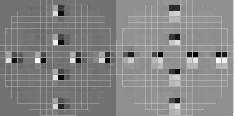
If the X0, Y0 is off by one subaperture, then you will see something like this.
Try adding/subtracting 16 pixels from the Y0 value (in this case) or X0 value and press CHECK LBWFS REG. Once you are no longer off by one subaperture, then go back to Step 1 and start again. |
 |
If the DM to LBWFS registration is not very good, then move LBS until it is, as described here. Then go back to Step 1 and start again. |
7. Press SET ORIGINS TO ZERO
8. Define and save the LBS position
Write down the values for the LBS position and hit DEFINE and SAVE in the SC GUI LBS screen.
9. Save the X0, Y0 values
Write down the X0, Y0 values and save them by hitting the SAVE X0, Y0 VALUES. This will save the X0 and Y0 values. Now you can continue with the calibrations.
9. Determine the 5x5 position
Now send the LBS to the 5x5 named position.
Take an image and record the x0, y0. Move LBS until the x0, y0 is the same as was calibrated for the 20x20 case. Ensure that there are 5x5 spots on the CCD. Then define and save the 5x5 named position for LBS.
Revision History:
- 07dec2009 MK
Added steps to D1 to put the nirc2 and optnirc2 focus position
to the same value. This should result in better image quality
with the loops closed.
- 04dec2009 ARC
Replace 'find an expert' with twiki link for junk.opd problems
(two places).
- 27nov2009 ARC
Fixed typo in first step of E2 (incorrectly
specified LBWFS cal tool for launch)
- 10sep2009 MK
Spelled out some GUI names. Added from what menues some of
the guis are launched.
- 30oct2008 ARC
Added Check Boxes.
- 18oct2008 ARC
5x5 no longer optional. Replaced all "SOD=SOD" with descriptive text.
Removed superfluous 20x20 step from D1.
- 29dec2010 jlyke
Added alternate tool startup method in step A2 and added checkbox
to step B1.
For more information, please contact
.
|
|