Version 1, 2018-Dec-12
1. Background
The KCRM commissioning plan includes relevant tests from on-sky commissioning plans drafted by Keck Staff and instrument development teams of previous Keck instruments so that the new hardware and software functionality are well tested and characterized. This document is expected to undergo periodic revision up through the commissioning period for KCRM.
To ensure that the necessary tasks are executed and that the relevant information is reported each task will have an assigned task leader. Task leaders are responsible for the test plan, execution, reduction, and analysis of the acquired data, and although they may enlist others to complete the task, they will ensure that the tasks are completed and reported on reasonable timescales.
Observers will be at the telescope acquiring data and running the tests. It is the responsibility of the task leader to ensure that task descriptions clearly identify all the necessary steps to acquire the data. Observers will work with task leaders by reviewing the observing plans for accuracy, completeness, and clarity.
Data Reducers will reduce and analyze the data and will contribute relevant information in test reports. The analysis of some tasks is completed during the observations, but the analysis of other tasks (e.g. zero points) is longer term, and for these tasks, it is important to identify who is responsible for analyzing and reporting these results.
This document is based on a spreadsheet available on the Keck KCRM documentation page. On that spreadsheet, each task is assigned a priority and an order of execution. The individual tasks are identified by task ID.
The same task ID appears here.
LIST OF Configuration STATES
2. Engineering Task List
The following list indicates the expected order of testing for
CARA-related KCRM tasks.
3. CARA Engineering Task List - Thematic
Introduction
This section provides detailed information on the tests
enumerated in the table above. Tests are grouped within major
categories. Organization of the information is very similar to
that used for the science team's tests, with minor changes
(e.g., observers are always assumed to be CARA staff). The
following information is provided for each:
Summary
P. Pointing Tests
P1. Initial target acquisition
Purpose: Verify the gross pointing of a target after absolute pointing of the telescope
Overview:
- Priority: H
- Depends on:
- Lead: Luca, Shui
- Sky time required: 45 minuntes
- Sky conditions: Moderate
Requirements:
- Reference pointing origin, REF, or similar, defined (pixel = center of the guider, mm = (0,0) )
- Pointing origin in guider pixel coordinates defined
- Plate scale of guider camera defined
- Orientation and flip of guider camera defined or estimated
Observing plan:
- Set rotator physical angle 0, stationary mode.
- Set exposure time to 1s. A short exposure time makes the rastering faster.
- Set the CA=0, CE=0, previously known good values, or expected estimated values.
- Slew to a 6th magnitude star near AZ=0, EL=50. This star will produce diffraction spikes. Following the spikes will lead to the star. Because of the brightness, it will be easy to identify.
- If the star does not appears on the guider image, change CA/CE in a spiral pattern with step size equals to one third of the image size. For example, if image size is 3x3 arcmin, then step size should be 1 arcmin.
- Stop the spiral search if CA and CE are greater than 200 arcsec in positive and negative direction.
- Revert to original CA/CE values.
- Set primary mirror focus mode 1000 um and start spiral search again with step size 90 arcsec.
- Stop the spiral search if CA and CE are greater than 600 arcsec in positive and negative direction.
- Slew to a globular cluster, the guider image should show some stars. Slowly move forward the center of the cluster where the density of the stars is the highest. Record the CA/CE values and repeat this procedure using these new CA/CE values as initial point.
- If the star still cannot be found at this point, verify the tertiary mirror position and the secondary mirror position and that the dome is not vignetting the view.
- Once the first star is found, if possible adjust pointing and mark collimation to record the CA/CE values. If adjust pointing is not possible because the guider camera orientation is not yet accurate, use hand paddle in CA/CE coordinates to move the star to the REF pixel and then mark collimation.
- Search the star catalog for 5 different near-by stars of magnitude between 8th and 11th and slew to their coordinates to verify pointing.
- Determine guider image orientation and repeat this procedure.
Reduction plan: N/A
Deliverables/Completion verification: The star appears near the center of the field of view of the guider
P2. Define REF pointing origin
Purpose: Define the fundamental pointing origin REF.
Overview:
- Priority: H
- Depends on: Guider working and first star acquired.
- Lead: Luca, Shui
- Sky time required: 20 minuntes
- Sky conditions: Moderate
Observing plan:
- Make sure that REF if defined, and that one of the two coordinates is zero.
- Slew to a bright star at high elevation, send it to REF, make sure the star ends in the REF pointing origin
Reduction plan:
Deliverables/Completion verification: REF pointing origin is determined and saved to the configuration database for TCSU. A star on the guider ends on the center of the guider if it is “sent to REF”.
P3. Define KCRM pointing origins
Purpose: Establish additional pointing origins, including MIRA. The list of pointing origins is:
- REF: Center of the guider (Already defined)
- IFU: Center of the field of view
Overview:
- Priority: H
- Depends on: Knowledge of the pixel positions of the slicers in the FP camera. Knowledge of the pixel scale of the guider in mm/pixel.
- Lead: Luca, Shui
- Sky time required: 60 minuntes
- Sky conditions: Moderate
Observing plan:
- Slew to a bright star at high elevation (50deg, 1hour from meridian), get a handpaddle in Xim,Yim coords, PA = 0, Rotator in stationary mode
- Insert focal plane camera, take an image and make sure we can see a star
- Center the star at REF on the guider
- Switch to the desired pointing origin (IFU)
- While looking at FPC images, move the star in Xim,Yim coordinates until it reaches the pixel position of the required pointing origin
- If we want a higher precision, measure the pixel position of the star (x1,y1), rotate the K-mirror PA to PA=180, remeasure the pixel position (x2, y2), move the star to the mid point between the two measurements.
- Save pointing origin (if TCSU, update database)
- Move to next pointing origin.
Reduction plan:
Deliverables/Completion verification: REF pointing origin is determined and saved to the configuration database for TCSU. A star on the guider ends on the center of the guider if it is “sent to REF”.
G. MAGIQ guider tests
G1. Guider orientation
Purpose: The test determines the angle of the guider image X/Y coordinates relative to the Xim/Yim coordinates.
Overview:
- Priority: H
- Depends on: Guider working and calibrated.
- Lead: Luca, Shui
- Sky time required: 60 minuntes
- Sky conditions: Moderate
Requirements:
- Rotator physical angle zero point defined or estimated (from off-sky tests)
- Plate scale of guider image defined (from design)
- TV angle defined or estimated (from design)
Observing plan:
- Set rotator physical angle 0, and stationary mode.
- Slew to mount coordinates AZ=0, EL=50.
- Start guider camera exposures and set exposure time to 2s. Adjust according on brightness of stars such that star trails can be seen on the guider image, see example below.
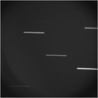
- The angle between the star trails and the horizontal axis is the guider image angle, TV angle modulus 180 deg.
- Verify that the star trails agree with the MAGIQ compass roses.
- Slew telescope in mount coordinates to AZ=180 and EL=50 and repeat the exposures.
- The average of the two angles for AZ=0 and AZ=180 is a better estimate of the TV angle.
- The value of TV angle includes the error of the rotator physical angle, which must be corrected with ROTBASE. By determining TV angle at AZ=0 and AZ=180, the rotator zero point error is cancelled out. The half the difference of the two angles at AZ= and AZ=180 is ROTBASE.
- Once the TV angle is determined, update MAGIQ and DCS/TCS configuration files and restart MAGIQ.
G2. Guider handedness
Purpose: Guider camera flip determines the handiness of the guider camera coordinate system
Overview:
- Priority: H
- Depends on: Guider working and calibrated.
- Lead: Luca, Shui
- Sky time required: 60 minuntes
- Sky conditions: Moderate
Requirements:
Guider camera orientation, TV angle, defined
Rotator zero point defined or estimated
Observing plan:
- Slew to a star at A=0 and EL=50, 10th magnitude.
- Set rotator angle to 0 deg and stationary mode.
- Start guider exposures.
- MAGIQ compass roses, East/North and AZ/EL, are approximately aligned depending on how well TV angle and rotator zero point are defined.
- For each of the following coordinates systems
- RA/DEC coordinates,
- AZ/EL coordinates, and
- TV X/Y pixel coordinates
- Perform offsets on each axis in positive and negative direction and verify that the motion and the direction match the direction of the compass roses
- Adjust TV angle and TV flip accordingly in configuration files and restart MAGIQ.
- There is also an additional image flip flag that is only in the MAGIQ configuration. This flag depends on the focal station, on the number of reflections and how the image is read out.
Reduction plan:
Deliverables/Completion verification: TVFLIP and TVANGL are correctly set, and saved on the corresponding configuration files. The star moves in the correct way on the guider when telescope moves are issued.
G3. Guide in sideral mode
Purpose: Main guiding mode. We want to verify that we can guide at different values of the PA
Overview:
- Priority: H
- Depends on: Guider working
- Lead: Luca, Shui
- Sky time required: 30 minuntes
- Sky conditions: Moderate
Observing plan:
- Slew to bright high elevation star
- Set PA=0, start guiding
- Save focal plane camera image
- Guide for 5 minutes
- Save focal plane camera image for comparison
- Repeat for other PAs as desired
Reduction plan:
Compare initial and final focal plane images, verify that the star motion is within acceptable tolerance
Deliverables/Completion verification:
The guider can guide at all PA values. The motion is within the acceptable tolerance.
G4. Guider plate scale and astrometry
Purpose: Verify the plate scale of the guider and compare with the expected values
Overview:
- Priority: H
- Depends on: Guider working
- Lead: Luca, Shui
- Sky time required: 15 minuntes
- Sky conditions: Moderate
Observing plan:
- Slew to dense field
- Acquire image
- Analyze offline
Reduction plan: Shui has a program to do this, almost in real time.
Deliverables/Completion verification: The guider plate scale and the astrometric solutions are determined.
G5. Guide (non sidereal)
Purpose: Verify that we can guide in non-sidereal mode
Overview:
- Priority: H
- Depends on: Guider working
- Lead: Luca, Shui
- Sky time required: 20 minuntes
- Sky conditions: Moderate
Observing plan:
1- Slew to non-sidereal target
2- Set PA=0, start guiding
3- Verify that the target maintains the position
Reduction plan:
Deliverables/Completion verification:
The guider can guide in non-sidereal mode
G6. Measure performance of the guider on large offsets
Purpose: If the high order distortion terms are correct, large offsets are accurate
Overview:
- Priority: M
- Depends on: Guider astrometry
- Lead: Luca, Shui
- Sky time required: 20 minuntes
- Sky conditions: Moderate
Observing plan: TBD
Reduction plan:
Deliverables/Completion verification:
G7. Guider differential flexure
Purpose: Not sure this is necessary at this time, as the gravity vector is constant, but here as a place holder in case it becomes necessary
Observing plan:
Reduction plan:
Deliverables/Completion verification:
Rotator tests
R1. Rotator zero point
Purpose: The rotator zero point is the offset of the rotator physical angle such that when rotator physical angle is zero the rotator is aligned with the vertical axis. This procedure should be used only after TV angle is determined
Overview:
- Priority: H
- Depends on: FPC on
- Lead: Morrissey with Luca and Shui
- Sky time required: 60 minuntes
- Sky conditions: Moderate
Requirements:ROTBASE is estimated
Observing plan:
Method 1
- Set rotator physical angle to 0 and stationary mode.
- Slew to mount coordinates AZ=0, EL=50.
- Start FPC camera exposures and set exposure time to 2s. Adjust according on brightness of stars such that star trails can be seen on the guider image.
- The angle between the star trails and the horizontal axis is the rotator zero point.
- Update ROTBASE in DCS/TCS configuration and reselect instrument.
Method 2
- Slew to an open cluster with at least 3 stars.
- Take an FPC image.
- Compare guider image with a DSS image overlaid with stars from a standard catalog.
- Match the visible stars in the guider image and from the star catalog and calculate the rotation angle. The angle is the rotation zero point.
- Repeat at different pointing locations and average the calculated angles.
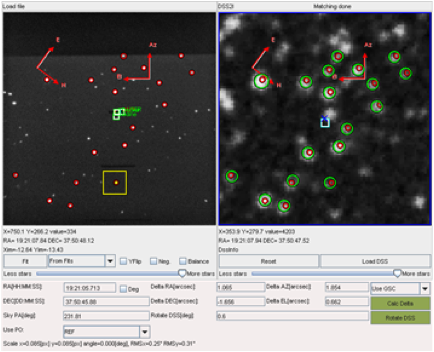
Update ROTBASE in DCS/TCS configuration and reselect instrument.
Reduction plan: Software written by S. Kwok
Deliverables/Completion verification:
R2. Determine rotator linearity
Purpose: Verify correct tracking of the rotator
Overview:
- Priority: H
- Depends on: Guider astrometry
- Lead: Morrissey
- Sky time required: 30 minuntes
- Sky conditions: Moderate
Observing plan: The idea is to acquire star trails at 0, 90, 180, 270 in stationary mode and verify that the stellar tracks are parallel or perpendicular to the CCD reference axis
- Point the telescope to (AZ, EL) = (180,70), mount coordinates. Set the rotator to 0°, stationary mode, so that stars trail along the long side of the array.
- Reduce rotator angle by 90° increments as many times as allowed by the rotator limits.
- Configure FPC for imaging.
- Set exposure time to 60 s. The images will thus contain vertical trails of stars exposed as the world turns.
- Acquire FPC exposures until at least one good star trail is achieved.
- Increase the rotator angle by 90° and acquire more star trail images.
- Repeat until no more 90° increments are possible
Reduction plan:
Deliverables/Completion verification:
R3. Determine rotator performance at high elevation
Purpose: Verify and characterize the performance of the rotator at increasing elevations to define the "keyhole"
Overview:
- Priority: M
- Depends on: Guiding in PA, rotator zero point
- Lead: Patrick
- Sky time required: 60 minuntes
- Sky conditions: Moderate
- Slicer: FPC; Filter: None/Cal-ND
Observing plan:
- Acquire a dense field at elevation > 60 degrees, 10 minutes before transit
- Start guiding, and aquire 30 seconds exposures with FPC once per minute
- Keep going until 10 minutes past transit
- Add 10 degrees to the elevation and repeat
Reduction plan:
Examine the focal plane camera for any smearing of the stellar images
R4. Characterize vignetting/pupil alignment
Purpose: Verify and characterize the possible presence of vignetting and the alignment of the pupil
Overview:
- Priority: M
- Depends on: Guiding in PA, rotator zero point
- Lead: Patrick
- Sky time required: 60 minuntes
- Sky conditions: Moderate
- Slicer: FPC; Filter: None/Cal-ND
Observing plan:
- Slew to an astrometric field that is at a high elevation (70-85)
- Select the KCWI PO and center the object
- Apply 500 nm of pmfm and determine if segments are vignetted on the FPC.
- Move the telescope to see if there are field points with increased vignetting.
- Remove pmfm and defocus secondary instead (25-30mm appears to be possible). This should allow imaging of the pupil. Verify that there is no vignetting and that moving the rotator does not affect pupil image other than rotating it on the detector. This test would also be possible by using the internal pupil imaging lens.
Reduction plan:
Examine the focal plane camera for any vignetting of the segments images
Focal plane camera tests
F1. Focal plane camera verification and preliminary characterization
Purpose: Acquire image of near-overhead star on the focal plane camera to verify functionality and image display. Get an on-sky handle of the camera response with and without the CAL ND filter in the beam.
*Note: This task, along with task 25 might be useful to perform before determining the pointing origin for the slicers (Task 4) or general pointing acquisition (Task 10). A live feedback of telescope moves should be more efficient than waiting on science CCD readout. We will have a fairly good idea of the relative location of the center of the FPC and the slicers from calibration activities (Task 27)
Overview:
- Priority: H
- Depends on: Guiding in PA
- Lead: Matt
- Sky time required: 30 minuntes
- Sky conditions: Moderate
- Slicer: FPC; Filter: None/Cal-ND
Observing plan:
- Telescope in PA mode, Image de-rotator at PA=0°
- Slew to a high elevation star (B=TBD) near the slicer PO, use this star for guiding
(If doing this before KCWI POs are established, may need to manually command offsets to land the star on the focal plane camera. Record this offset, once done)
- Make sure CAL ND filter is retracted
- Take a short exposures (t = TBD)
- Verify that the images are being displayed properly on the ds9 window
- Make sure images are not saturated, slew to a dimmer nearby star if so, repeat
- Take a series of images and a stack of images
- Insert CAL ND filter, verify telescope does not lose tracking
- Take a longer exposure (t=TBD)
- Take a series of images and a stack of images
- Verify image display in ds9 and approximate reduction in flux
- Retract CAL ND filter
Reduction plan: Inspect saved images offline, verify ND filter acts as expected. Compute rough sensitivity.
Deliverables/Completion verification: A first pass estimate of the camera throughput and refined (but still not final) B-mag to exposure time calculator for FPC with and without the ND filter.
F2. Focal plane camera handedness and plate scale
Purpose: Measure the plate scale and handedness of the focal plane camera
Overview:
- Priority: H
- Depends on: Guiding in PA, FPC verification, REF pointing origin
- Lead: Matt, with Shui and Luca
- Sky time required: 60 minuntes
- Sky conditions: Moderate
- Slicer: FPC; Filter: None/Cal-ND
Requirements:
- Guider angle and flip defined
- Rotation zero point defined
- Instrument angle defined or estimated
- A pointing origin within the field of view of the instrument
Observing plan:
- Slew to a star, 10th to 11th magnitude and center on REF.
- Change to the instrument pointing origin.
- Put PMFM = 300um or greater depending on the plate scale of the instrument detector.
- Take an image.
- Find the segments #22, #9, #2, #5, #15 and #31. They are aligned with the vertical axis.
- Segment #22 points to lower elevation and #31 points to higher elevation.
- Calculate the centroids of the said segments.
- The centroids must lie on a line.
- The angle between this line and the columns of the detector is the instrument angle. Depending on the flip of the image, the angle can be the 180 deg complement.
Reduction plan: Analyze the images offline (S. Kwok’s software) Centroid the star in each image compute plate scale and refine tkrose.
Deliverables/Completion verification: Refined tkrose and FPC plate scale
Focal Plane Camera Tests
F3. FPC limiting magnitude
Purpose: Determine the limiting B magnitude of the Focal Plane Camera for a SNR of 5 in 30 seconds. The FPC field of view is small 18 x 16 arc seconds unvignetted
Overview:
- Priority: L
- Depends on: Guiding in PA, FPC verification
- Lead: Matt
- Sky time required: 30 minuntes
- Sky conditions: Moderate
- Slicer: FPC; Filter: None/Cal-ND
Observing plan:
Option 1:
- Telescope in PA mode with suitable PA angle
- Slew to a dense star field (TBD)
- Take a short (1 s) exposure to estimate time T to saturation
- Take a series of T length exposures to add up to 30 s, repeat. Save all images
Option 2:
- Telescope in PA mode with PA=0°
- Slew to a series of high elevation stars from B=18 in dB ~ 1 increments, preferably of the same or very similar spectral type
- Take a series of t = 1 s images for each star, save images
- With a single star in view, use a script to quickly determine the acquired SNR. Script could (should?) generate exposure times for dimmer stars
- Be flexible in magnitude increments, skip steps if SNR high to converge on limiting magnitude as quickly as possible
- Once limiting magnitude found, confirm with object of similar brightness
Reduction plan:
Option 1:
Reduce offline using standard astronomical tools (SExtractor) and a deep star catalog (e.g., USNO B 2.0).
Option 2:
Use script to compute magnitudes (verify later offline). Need to write script.
Deliverables/Completion verification:
Limiting magnitude of the FPC for a point source in a 30 s exposure. Exposure T calculator?
F4. FPC astrometric solution
Purpose: Find the astrometric solution for the focal plane camera. Note, that the focal plane camera has a very small field of view (comparable to the medium KCWI slicer, or 15 x 20 arc seconds). As such, the expected distortions are not anticipated to be particularly large.
Overview:
- Priority: L
- Depends on: Guiding in PA, FPC verification
- Lead: Matt
- Sky time required: 20 minuntes
- Sky conditions: Moderate
- Slicer: FPC; Filter: None/Cal-ND
Observing plan:
- Telescope in PA mode with suitable PA angle
- Ensure FPC images are being saved
- Slew to desired dense star field with 10 -20 stars in the FOV and start guiding
- Take a short FPC image to establish suitable exposure time, t
- Take a series of longer exposure times to build up good SNR (>5) in the majority of visible stars
Reduction plan: Reduce data offline using standard astronomical tools or Shui's software
Deliverables/Completion verification: Astrometric solution for FPC (quaternion? WCS?)
T. Telescope tests
T1. Focus the telescope (manual, Autofocus)
Purpose: Focus the secondary mirror
Overview:
- Priority: H
- Depends on:
- Lead: Matt/Shui
- Sky time required: 30 minuntes
- Sky conditions: Moderate
Requirements:
- the FPC is parfocal to the slicers
- the guider is parfocal to the FPC and to the guiders
- both requirements are met via internal calibration (SEE MATT)
Observing Plan:
- Slew to a bright star at high elevation
- Manually adjust the telescope focus to achieve the best visually inspected image quality
- run Autofocus on the guider
Reduction Plan:
T2. Acquire images for MIRA calibration
Purpose: Take images with FPC at different PMFM modes to determine rotation and handedness of images for MIRA analysis.
Overview:
- Priority: H
- Depends on:
- Lead: Matt/Shui
- Sky time required: 20 minuntes
- Sky conditions: Moderate
Observing plan:
- Slew to MIRA star at an elevation of 70 and hour angle 2 hours east
- Center the star on the FPC
- Apply 250 nm of PMFM
- Acquire FPC image, verify exposure
- Kick out a segment, acquire second image
Reduction plan: Shui to analyze in real time and make corrections to MIRA script if necessary. This is an update done in real time.
Deliverables/Completion verification: MIRA images are characterized in position and rotation angle.
T3. Verify execution of MIRA script and calibrate MIRA
Purpose: Run the MIRA script and verify it correctly measures focus and tilt (Optional)
Overview:
- Priority: H
- Depends on: Successful run of the MIRA script in the afternoon, with PMFM disabled
- Lead: Luca/Shui
- Sky time required: 60 minuntes
- Sky conditions: Moderate
Observing plan:
- Slew to MIRA star at an elevation of 70 and hour angle 2 hours east
- Center the star on the FPC
- Focus the telescope using alternate method (Autofocus)
- Run MIRA script
- Verify that MIRA requires no focus correction
- Apply piston offset
- Verify that MIRA predicts the piston correction
- Repeat for different values of piston
Reduction plan:
Deliverables/Completion verification: MIRA correctly corrects for piston offsets.
Science tasks
S1. Object acquisition
Purpose: Show that target objects can be positioned in the science field of view. Determine the focus offsets of the FPC and the three image slicers in zero order.
Overview:
- Priority: H
- Depends on: FPC verification
- Lead: Morrissey
- Sky time required: 120 minuntes
- Sky conditions: Moderate
- Slicer: FPC; Filter: Red blocking; Camera: in Zeroth order
Observing plan: This task is complementary to Task 11, KCWI Pointing Origins.
- Insert the focal plane camera (FPC) in the field
- Align the science camera for zero order imaging
- Remove the N&S mask
- Insert the red blocking filter
- Remove the grating
- Verify the spectrograph is in focus with a flat field calibration arc lamp image
- Acquire a star (within 1 hour of zenith) in the guider
- Center the star in the guider
- Focus the guider
- Begin guiding
- Download a FPC image, verify properly exposed star image
- Capture FPC images at different telescope focus positions
- Refocus the guider at the FPC focus position
- Verify star image is in a location that will be captured by all 3 slicers
- Offset star in guider field if necessary
- Insert the large IFU slicer
- Download an image, verify properly exposed star image
- Focus the telescope of the large slicer
- Repeat for the medium and small slicers.
Reduction plan: Offline? The reduction plan would be to use a modified form of CWI_Center_Star on the raw KCWI images to determine offsets from the slicer origins. Images can be examined in ds9 to determine best focus.
Deliverables/Completion verification: The guider images, pointing offsets, focus offsets and science images should all be captured. If a star on the guider can be successfully offset and focused for each IFU and the Focal Plane Camera, then the task is complete
S2. Spectrum acquisition
Purpose: The purpose of this task is show that the instrument properly acquires seeing-limited spectra. It is complementary to Task 18 (S2)
Overview:
- Priority: H
- Depends on: FPC verification, Object acquisition (S1)
- Lead: Matt
- Sky time required: 180 minuntes
- Sky conditions: Moderate
Observing plan:
To the extent that standard stars can be observed, this task overlaps Task 34 (S12)
- Insert the large slicer in the field
- Remove the N&S mask
- Insert the red blocking filter
- Insert the RH3 grating
- Configure for observations
- Verify the spectrograph is in focus with a flat field calibration arc lamp image
- Acquire a star (within 1 hour of zenith) in the guider
- Center the star in the guider (presuming no offset is required for any slicer)
- Focus the guider
- Begin guiding
- Download an image, verify properly exposed star image
- Focus the telescope on the large slicer
- Repeat 11-12 for the medium and small slicers.
- Reconfigure for RM grating with the large slicer
- Acquire a flat field calibration arc lamp image to verify spectrograph focus
- Determine best telescope focus for the RM grating
- Repeat 14-16 for the medium and small slicers
- Reconfigure for BRL grating with the large slicer
- Acquire a flat field calibration arc lamp image to verify spectrograph focus
- Determine best telescope focus for the BL grating
- Repeat 18-20 for the medium and small slicers
Reduction plan: We will be able to determine best focus from visual analysis of the data at the telescope, but more detailed analysis offline may be desired for the final result. It should be possible to use the focus offsets determined in Task 33 rather than refocusing each slicer/grating combination. It depends on how stable to telescope focus is and whether there is a benefit to refocusing to provide confidence in the measured spatial resolution.
Deliverables/Completion verification: The Hbeta spectrograph focus should be recorded for each grating and slicer combination. Assuming 10 images are required for each focus curve, there will be 90 images and 9 instrument configurations required to complete this task. The task is complete when seeing-limited spectra have been acquired in all modes.
S3. Spectral throughput
Purpose: Spectrophotometric standards will be used to determine the total throughput of the instrument (and telescope and sky).
Overview:
- Priority: M
- Depends on: FPC verification, Object acquisition (S1)
- Lead: Morrissey
- Sky time required: 180 minuntes
- Sky conditions: Moderate
Observing plan:
- Insert the large slicer in the field
- Remove the N&S mask
- Insert the red blocking filter
- Insert the RH3 grating
- Acquire a standard star (within 1 hour of zenith) in the guider
- Center the star in the guider (presuming no offset is required for any slicer)
- Focus the guider (presuming the guider focus has been chosen to be confocal with the science focal plane)
- Begin guiding
- Configure for observations
- Verify the spectrograph is in focus with a flat field calibration arc lamp image
- Download an image, verify properly exposed star image
- Repeat 10-11 for the medium and small slicers.
- Reconfigure for RM grating with the large slicer
- Acquire a flat field calibration arc lamp image to verify spectrograph focus
- Repeat 13-14 for the medium and small slicers
- Reconfigure for RL grating with the large slicer
- Acquire a flat field calibration arc lamp image to verify spectrograph focus
- Repeat 16-17 for the medium and small slicers
- As time permits, the camera/grating may be configured to other wavelengths to capture the full range of BL, BM and BH with at least one slicer.
Reduction plan: Reduction will be offline using the pipeline and probably one independent method for verification.
Deliverables/Completion verification: The effective area of the system in each mode should be documented in a report with an attempt to back out the efficiency of the instrument alone.
S4. Spectral throughput for all slices
Purpose: Measure the relative throughput across the science field of view
Overview:
- Priority: L
- Depends on: FPC verification, Throughput (S3)
- Lead: Morrissey
- Sky time required: 240 mins
- Sky conditions: Thin clouds
Observing plan: The plan is to measure the flat field of the instrument using illumination from the sky, and to scale this to the measured standard star efficiency. For the purposes of generating a high signal-to-noise flat field, twilight illumination will be useful.
- Insert the large slicer in the field
- Remove the N&S mask
- Insert the red blocking filter
- Insert the RH3 grating
- Point telescope to the zenith during twilight
- Configure for observations
- Verify the spectrograph is in focus with a flat field calibration arc lamp image
- Download an image, verify properly exposed star image
- Record enough images to create a high S/N flat (~1%)
- Repeat 6-9 for the medium and small slicers.
- Reconfigure for RM grating with the large slicer
- Acquire a flat field calibration arc lamp image to verify spectrograph focus
- Record enough images to create a high S/N flat (~1%)
- Repeat 11-13 for the medium and small slicers
- Reconfigure for RL grating with the large slicer
- Acquire a flat field calibration arc lamp image to verify spectrograph focus
- Record enough images to create a high S/N flat (~1%)
- Repeat 15-17 for the medium and small slicers
- As time permits, the camera/grating may be configured to other wavelengths to capture the full range of BL, BM and BH with at least one slicer.
Reduction plan: Data will be reduced offline using a combination of the pipeline and custom software.
Deliverables/Completion verification: The absolute throughput as a function of wavelength for each configuration and position (flat field vs wavelength) should be available to observers to aid in the reduction of their data.
S5. Measure the effect of scattered light
Purpose: Measure the effect of moon light contamination
Overview:
- Priority: L
- Depends on: Object acquisition
- Lead: Engineering
- Sky time required: 90
- Sky conditions: Clear
Observing plan:
- Slew to selected position near the moon
- Acquire spectrum
- Slew to next position (repeat at 5,10,15,20, 30 degrees away)
- Acquire spectrum
Reduction plan: Full pipeline reduction
Deliverables/Completion verification: The produce is a table of sky background contribution as a function of moon distance, and a recommendation to the users as to how close to observe to the moon.
S6. Rehearsing phase of N&S
Purpose: Verify the correct functioning of the S&N rehearsal phase.
Overview:
- Priority: H
- Depends on: Guider working correctly, N&S plannig test on hand-made script
- Lead: Don
- Sky time required: 30
- Sky conditions: Moderate
Pre-observing plan:
- Pick a nearby galaxy with obvious emission features.
- Set exposure time such that observation will produce high S/N imaging.
- Pick a blank background field with no point sources.
- Generate finder charts for two fields for verification.
- Generate script with N&S planning tool or by hand.
Observing plan:
- Run N&S execution tool.
- Load script and set to rehearsal mode in GUI.
- Acquire science field
- Verify science field and guide star coordinates.
- Begin guiding.
- Initiate rehearsal move to background.
- Verify background field and guide star coordinates.
- Save script with guide star adjustments.
- Complete rehearsal mode.
- Verify return to science field with guiding on.
- Verify updates to script.
Reduction plan: None.
Deliverables/Completion verification: Verification of correct functioning of N&S rehearsal mode, initial estimate of rehearsal overhead (time).
S7. Execution phase of N&S
Purpose: Verify the correct functioning of the S&N rehearsal phase.
Overview:
- Priority: H
- Depends on: Guider working correctly, N&S rehearsing
- Lead: Don
- Sky time required: 60
- Sky conditions: Moderate
Observing plan:
- After completion of N&S rehearsal phase, initiate execution phase.
- Verify nods with guider display.
- Verify completion of execution and readout of image.
- Verify correct shuffling of charge by display of science image in ds9.
- If time permits, verify pausing and aborting the execution phase.
Reduction plan: Reduce data offline with KDERP. Verify N&S subtraction.
Deliverables/Completion verification: Verification of correct functioning of N&S execution mode and operational procedure for operating the N&S execution script, initial estimate of N&S overhead (time).
S8. Verify and Characterize DAR compensation
Purpose: The MAGIQ guider in the KCWI Blue Channel instrument guides in I band, whereas the instrument observes in U, B, and V. Differential atmospheric refraction will lead to smearing of objects on the science detector. The purpose of this task is to verify that the magnitude and direction of the DAR compensation built into guiding is correct. This can easily be done in bright time and can (probably) be done in nautical twilight or dimmer sky.
Overview:
- Priority: M
- Depends on: Guider working correctly and astrometrically calibrated
- Lead: Matt, Don
- Sky time required: 90
- Sky conditions: Moderate
- Slicer: Small, Grating: BL; Filter: Blue; Polarizer: Out; Mask: Out
Observing plan:
Sequence 1:
- Telescope in PA mode
- Slew to a bright (U = TBD) blue star at high airmass (setting z = 2 or rising z = 3 ) with Dec close to 19.8°
- Set PA to align the dispersion direction (elevation) with the long axis of a slice
- Offset star to the center of slice 10, configure the DAR tool/software to compensate and track at 380 nm
- Take science exposures of a few seconds to and adjust exposure time t to get good SNR
- Take a cadence of exposures as the object rises (sets?) for 40 minutes
- Record MAGIQ guider generated offsets and guider images during this time
May need a second sequence to verify compensation angles, or at another slicer orientation? These tests can be quite time consuming, though.
Reduction plan:
Reduce data through KCWI pipeline offline. Determine shift of object at different wavelengths within the BM range – making sure that the configured wavelength (380 nm) remains fixed. Do this by looking at narrowband images from the cube around 380 nm. Verify other wavelengths shifting in appropriate fashion
Deliverables/Completion verification: Verification that the DAR compensation is valid
S9. Verify Polarizer Capability
Purpose: KCWI is equipped with a linear polarizer that can be inserted into the beam and rotated to an arbitrary angle. Three images of an object, with the polarizer set to 3 different angles, allow for the determination of the amount and direction of the linear polarization of the source. The purpose of this test is to verify this capability and to refine the polarizer offset angle.
Overview:
- Priority: M
- Depends on: Guider working correctly, FPC working, spectral acquisition
- Lead: Matt
- Sky time required: 45
- Sky conditions: Thin
Observing plan:
- Telescope in PA mode with PA=0°
- Instrument configured as follows:
-
Slicer |
FPC |
Grating |
BL |
Filter |
FPC-ND? |
Mask |
No |
Polarizer |
Out |
|
- Slew to a polarimetric standard (LRIS documentation is a good resource:
http://www2.keck.hawaii.edu/inst/lris/polarimeter/pol_quickref.html)
- Offset to slicer pointing origin, begin guiding
- Take a series focal plane image of the object (determine exposure time and save all FPC images)
- Insert polarizer into the beam with and take a series of images with polarizer at angle P=0°, 120°, 240°. Instrument setting:
Slicer |
FPC |
Grating |
BL |
Filter |
FPC-ND? |
Mask |
No |
Polarizer |
Yes (0°, 120°, 240°) |
|
Other requirements |
Guiding |
|
- Repeat steps 2 to 6 for another standard
- Turn off focal plane camera, insert large slicer:
-
Slicer |
Large |
Grating |
BL |
Filter |
Red-Blocking |
Mask |
No |
Polarizer |
Yes (0°, 120°, 240°) |
|
Other requirements |
Guiding |
|
- Offset object to center on slice 11
- Rotate polarizer to P=0°, 120°, 240° and acquire science image with good SNR at each setting
- Remember to take a full set of calibrations, including polarizer flats in the afternoon/morning
Reduction plan: Reduce science data offline through the KDERP. Analyze FPC images offline. Determine fluxes for the three polarization images and combine to deduce the degree of linear polarization and direction. Compare with and calibrate against tabulated values.
Deliverables/Completion verification: Verification of polarizer capability and refinement of polarizer 0 angle.
S10. Verify Polarizer Capability for Faint Objects
Purpose: Explore the sensitivity of the KCWI polarimeter to faint diffuse sources. This could be part of the science verification, though in that case the target selected will be dimmer, and required time longer (200 minutes, min).
Overview:
- Priority: M
- Depends on: Guider working correctly, FPC working, spectral acquisition, polarizer verified
- Lead: Matt
- Sky time required: 130
- Sky conditions: Clear, Dark
Slicer |
Large |
Grating |
TBD |
Filter |
Blue |
Mask |
IN |
Polarizer |
In |
|
Other requirements |
|
|
Observing plan:
- Prepare a nod-and-shuffle observation for the selected extended object
- Telescope in PA mode, PA angle set to selected target
- Instrument in N+S mode, large slicer, filter, grating TBD
- Slew to known polarized extended/diffuse nebula (TBD)
- Align on target and rehearse N+S script
- Insert polarizer and rotate to P=0°
- Rotate polarizer to P=120°
- Rotate polarizer to P=240°
- Retract polarizer
- Remember to take appropriate calibrations in the afternoon/morning
Reduction plan: Offline, using KDERP, same concept as task 32.
Deliverables/Completion verification: Estimate of the sensitivity of polarimetric measurements with KCWI Blue.
S11. Direct Imaging Mode
Purpose: Verify direct imaging data acquisition and image reconstruction
Overview:
- Priority: M
- Depends on:
- Lead: Matt/Don
- Sky time required: 20
- Sky conditions: Moderate
Observing plan:
- Telescope in PA mode with PA angle set appropriately for the target (most likely PA=0° is OK)
- Slew to target (TBD, open cluster, outskirts of a cluster, dense star field, etc. – want 10 – 20 stars on the large slicer)
- Offset target to slicer pointing origin, start guiding
- Focal plane camera in
- take short exposure of field with focal plane camera
- Large slicer in
- take a science exposure of field, short (t = tbd)
- take a science exposure of field, long (t = tbd)
- Medium slicer in
- take a science exposure of field, short (t = tbd)
- take a science exposure of field, long (t = tbd)
- Small slicer in
- take a science exposure of field, short (t = tbd)
- take a science exposure of field, long (t = tbd)
Reduction plan: Reduce offline with KDERP. FPC images using standard astronomical image reduction tools.
Deliverables/Completion verification: Confirm direct imaging works, estimate sensitivity from stars in the field.
S12. Charterize sky subtraction
Purpose:Characterize the accuracy of sky subtraction using nod-and-shuffle source/background subtraction. The simplest approach is to first perform a series of shuffle with no nod exposures. The precision can be measured by summing the source and the background spectrum and looking at the subtraction residuals vs. the expected Poisson noise. Then the same experiment can be performed using either a blank field target or science target as “Source”, with an offset “Background” field. Ideally this would be done to the deepest level possible with multiple gratings and slicers. This is not practical during commissioning. More realistically we will select 3 settings, RH2 with Small slicer, RM with medium slicer, and RL with large slicer in order to span the resolution space from R~1000 to R~20,000.
Targets: Blank sky, high latitude. Lyman alpha blob. Lyman break galaxy halo.
Observing plan:
Sequence 1 (Shuffle/No Nod):
- Prepare a nod-and-shuffle observation for the selected extended object
- Telescope in PA mode, PA angle set to selected target
- Instrument in N+S mode, large slicer, filter, grating BL
- Slew to blank sky location (no bright stars, no galactic cirrus, high galactic latitude). Ideally no elevation greater than 90° to eliminate rapid pupil rotation. Align on target. Start guiding
- Perform standard NAS script but disable telescope moves. Utilize 2 min integrating time, 10 total source/10 total background exposures
- Obtain TBD exposures
Sequence 2 (Nod and Shuffle)
- Prepare a nod-and-shuffle observation for the selected extended object
- Telescope in PA mode, PA angle set to selected target
- Instrument in N+S mode, large slicer, filter, grating BL
- Slew to blank sky location (no bright stars, no galactic cirrus, high galactic latitude). Start guiding.
- Align on target and rehearse N+S script
- Perform standard NAS script. Utilize 2 min integrating time, 10 total source/10 total background exposures
- Obtain TBD exposures
Sequence 3 (Shuffle no nod): repeat sequence 1 with BH2, small slicer
Sequence 4 (Nod and shuffle): repeat sequence 2 with BH2, small slicer
Sequence 5 (Shuffle no nod): repeat sequence 1 with BM, medium slicer
Sequence 6 (Nod and shuffle): repeat sequence 2 with BM, medium slicer
Reduction plan: Reduce data through KCWI pipeline offline. Determine residuals in standard source minus background data cube, compare to expected noise.
Deliverables/Completion verification:
S13. Charterize object contrast
Purpose: Characterize the contrast of an object vs positon
Possible targets: Bright blue SAO stars
Observing plan:
- Telescope in PA mode
- Instrument large slicer, BL grating
- Slew to a bright (U = TBD) blue star at low airmass
- Offset star to the center of slice 12
- Take science exposures of a few seconds to and adjust exposure time to get maximum DN without saturation
- Obtain TBD exposures. Dither ½ slice between exposures
- Repeat 2-6 with small slicer, BH2, and medium slicer,BM
Reduction plan:
Reduce data through KCWI pipeline offline. Co-add data cubes after alignment. Determine PSF distribution out to edge of slicers.
Deliverables/Completion verification:
Broad wing PSF vs. slicer/grating. Verify intensity of scattering wings is below 1.e-3 beyond 5 arcsec radius in all directions.
S14. Charterize astrometric accuracy
Purpose: Characterize the accuracy of astrometric solution in reduced data cubes using direct imaging and BL grating and all three slicers.
Possible Targets: M13, M36, other open clusters
Observing plan:
- Telescope in PA mode
- Slew to a open star cluster with >10 stars per small slicer field
- Take science exposures of a few seconds to and adjust exposure time to get good SNR
- Record FPC prior to each science exposure
- Take a series of ~10 guided exposures dithering ¼ slice perpendicular to slices between exposures
- Take a series of 10 guided exposures dithering 2 arcsec parallel to slices.
- Take a series of 10 guided exposures offsetting rotator PA by 10° between exposures
- Store MAGIQ guider and FPC camera images for all exposures
Reduction plan:
Reduce data through KCWI pipeline offline. Determine centroid positions of all stars in data cubes for each dither/PA position. Determine residuals of KCWI and GSC/other astrometric reference catalog, compare to requirement, and determine any systematic trends of residuals vs. star/slice/Position Angle.
Deliverables/Completion verification:
Verification that the astrometry requirement of 0.2 arcsec (rms) knowledge is met.
S15. Charterize spectral resolution over full field of view
Purpose: Characterize the highest possible spectral resolution using the highest dispersion gratings with the small slicer. Characterize the spectral resolution for point sources using the medium and large slicers and BH2.
Possible Targets: Dwarf elliptical galaxies with velocity dispersion <10 km/s. Bright stars. Globular clusters (many choices). Galactic nebulae (PNe or reflection nebula).
Observing plan:
Sequence 1: Bright star
- Telescope in PA mode
- Slew to star
- Take science exposures of a few seconds to and adjust exposure time to get good SNR
- Take exposure required to obtain good SNR in 1”x1” pixels
- Take a grid of exposures 2” x 5” over slicer
- Take 2 settings per grating for all 3 gratings to cover full 3500-5600Å bandpass
Sequence 2: Globular cluster (good seeing)
- Slew to Globular Cluster
- Take science exposures of a few seconds (fast/4amp) and adjust exposure time to get good SNR
- Take deep exposure of center of GC.
- Take 2 settings per grating for all 3 gratings to cover full 3500-5600Å bandpass
Sequence 3: Galactic nebula
- Slew to nebula
- Take science exposures of a few seconds (fast/4amp) and adjust exposure time to get good SNR
- Take deep exposure of center of GC.
- Take 2 settings per grating for all 3 gratings to cover full 3500-5600Å bandpass
Sequence 4: Elliptical Galaxy
- Slew to galaxy
- Take science exposures of a few seconds (fast/4amp) and adjust exposure time to get good SNR in 2” x 2” voxels
- Take deep exposure of center of galaxy.
- Take 2 settings per grating for all 3 gratings to cover full 3500-5600Å bandpass
Reduction plan:
Reduce data through KCWI pipeline offline. Measure spatial resolved spectral resolution. Measure spectral resolution in light bucket mode.
Deliverables/Completion verification:
Verification that the on sky spectral resolution is the same as that measured using the Cal system and meets requirements.
4. List of instrument states
- FPC, mirror=sky
- BH3 at Hbeta, large slicer
- BM at Hbeta, large slicer
- BL at Hbeta, large slicer
- Repeat for medium and small slicer
- BH2 @ <TBD> for spectral resolution across field of view (BH3 @ HBeta already done, BH1 not available)
- total: 10 configurations
Appendix
SKYPA Definitions
Keck instruments generally have multiple sky position angles
defined. The fundamental definition of the sky position angle
(SKYPA) is the angle between celestial north and the guider YIM
axis. Accordingly, the sky position
angle which will be saved in the image headers and displayed on
FACSUM will not be the fundamental sky position angle
as defined in KSD 40.
The following SKYPA options are proposed for KCWI:
| Name |
Description |
Offset*
[°] |
| SKYPA0 |
Perpendicular to slicers |
0 |
| SKYPA1 |
Guider column (YIM)** |
0 |
| SKYPA2 |
FPC column |
0 |
Notes:
- *Offsets are approximate and are expressed relative to
the fundamental SKYPA, SKYPA1
- **This is the fundamental SKYPA (i.e., the one displayed
on FACSUM and saved in image headers as keyword ROTPOSN) and
has zero offset by definition
Considerations Regarding Rotator Calibrations (TBD!!)
According to KSD 40, guider YIM shall define the rotator angle
and hence the fundamental SKYPA, SKYPA1. However, the guider is
neither the most stable not the most astronomically important
element in the focal plane: the slicer mechanism is of greater
utility. This suggests the following plan for achieving
rotational alignment of the focal plane systems:
- The longslit orientation shall form the basis of
alignment in the focal plane.
- The CCD dewar (or, more likely, a chosen CCD within the
dewar) shall be adjusted rotationally until it is well
aligned with the slitmask.
- The TV guider detector shall be adjusted rotationally
until it is well aligned with the slitmask.
This suggests the following order of operations to define
DCS parameters:
- Set TVFLIP appropriately for guider image
- Set TVANGL to 0° or 180°
- Set ROTZERO to produce images aligned to TV guider
rows/columns
- Re-init rotator
- Adjust ROTBASE keyword value to produce images aligned
precisely to CCD rows/columns
- Set INSTANGL to +90° or -90° and verify operation