Integral Field Unit
Contents
Summary
This document provides an observers' overview of the capabilities of and operational procedures for the ESI Integral Field Unit.Background
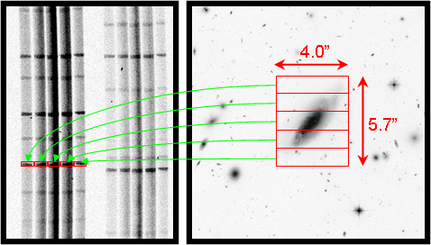
The ESI Integral Field Unit (IFU) is a device that can be used (instead of the standard echellette slits) to obtain cross-dispersed ESI spectra over a contiguous 4.0×5.7 arcsec area of the sky. The principal use for the unit is to observe extended targets which are larger in apparent size than the typical slit width of about 1.0 arcsec. As shown below, the device employs an image slicer which rearranges the retangular field of view into five separate spectra covering 20 arcsec of slit length.
|
|
Simulated ESI IFU target and spectrum. The IFU re-arranges the input
image to produce adjacent spectra from 5 contiguous regions.
Right: Simulated target, a galaxy much wider than the typical
ESI slit. The red boxes indicate the 5 contiguous
1.3×4.0 arcsec “slices” on the sky observed with
the IFU.
Left: Simulated spectrum consisting of 5 individual spectra
correponding to the 5 IFU slices.
|
Configuration
As of this writing, the ESI IFU is installed in the top (aperture mask or APMSK) wheel of the ESI triple wheel assembly, so it is always available for observer use. To use it, simply select the named setup IFU in the ESI dashboard, which will change the following settings:
| Keyword | Value |
|---|---|
| SLMSKNAM | IFU |
| APMSKNAM | Decker |
| DWFILNAM | Clear_S |
| IMFLTNAM | out |
| LDFLTNAM | out |
| PRISMNAM | in |
| COLLFOCR | -190000 |
| WINDOW | 0 0 0 2048 4096 |
| BINNING | 1 1 |
Focusing
The IFU slitlets are not in the same plane as the echellette-mode slits, and thus both the telescope and the slit-viewing guider must be refocused when using the IFU in order to produce a focused image at the IFU slit plane and on the guider. This following section gives the gory details.Focusing the Instrument
Typically, the observer does not need to measure the IFU focus, since this is measured by the Support Astronomer and stored in the IFU named setup file mentioned above. If necessary, the instrument focus appropriate for the IFU is best measured as follows:- Put telescope at dome flat position.
- Turn on the dome fluorescent lamps to provide adequate illumination.
- Configure ESI via IFU named setup.
- Open ESI hatch.
- Set observation type to DmFlat and exposure time to 2 sec.
- Acquire images at 20,000 step intervals over the range -190,000<COLLFOCR<-70,000.
- Measure the spectral width of a fiducial spectral feature.
- Launch IRAF.
- Display image to ds9.
- Run imexamine.
- Use command epar kimex to update the value of naverage to 11.
- Center cursor on feature and press k key to fit a Gaussian profile in the row direction.
- Record FWHM as a function of COLLFOCR. Save COLLFOCR and FWHM values in a 2-column text file.
- Analyze the results in IDL.
- Launch IDL v7.0.
- Edit and execute script ~gwirth/lib/idl/esieng/do_esi_ifu_focus.pro
- Note the best focus value (Xbest) specified on the plot produced by the script.
Focusing the Telescope with ESI IFU
As mentioned above, the ESI IFU slitlets lie outside of the focal plane shared by the remaining ESI slitlets, requiring the folowing special procedure for focusing:- Configure for R imaging. Configure ESI for R-band imaging by loading the Rimage named setup file.
- Run MIRA. Have the OA select an appropriate star for running MIRA. Execute MIRA and analyze results to focus the telescope.
- Configure for IFU. Configure ESI for IFU spectroscopy by loading the IFU named setup file.
- Adjust telescope and guider focus. Using the ifuFocusComp widget, select IFU on (Slit guiding) mode to compensate for the differing focal planes of the IFU slitlets and focal plane mirror.
- Run AUTOFOC. Have the OA place a star on the IFU mirror and complete AUTOFOC to refocus the secondary mirror for the IFU position.
- Re-adjust guider focus for pickoff mirror. (Optional) If you will be using the direct imaging technique for aligning the IFU on your target, or if no suitable guide star is available on the IFU mirror, then you will want to guide off the usual ESI pickoff mirror. Using the ifuFocusComp widget, select IFU on (Pickoff guiding) mode to compensate for the differing foci of the IFU and pickoff mirror.
Target Acquisition/Alignment
We offer several methods for putting your target onto the IFU slitlets, described below.| Method | Procedure | Suitable for | Pros | Cons |
|---|---|---|---|---|
| Guider Centering | Tweak the IFU position, center star at fiducial position and return to IFU position. | Any target which is visible on the guider. | Fast. | Centering accuracy only fair. |
| Spectral Centering | Acquire short IFU spectrum and analyze distribution of light within slitlets | Relatively compact targets which have bright continuum or a strong emission line in the spectrum | Most accurate centering method. Requires no change in instrument mode or telescope focus. | Slower. Won't work well on faint or diffuse targets. |
| Direct Imaging | Acquire direct image of target and send corrections until it is at the desired IFU center | Targets which are relatively compact and visible in broadband images of <2 minutes | Centering accuracy good. | Slow. Requires change in telescope, guider, and instrument focus. |
| Imaging of offset star | Acquire direct image of offset star, send corrections until it is at the desired IFU center, then offset to target | Any target with a measured offset to a star within about 1 arcmin | Only method that works for faint/invisible targets. Good centering if offset star is nearby. | Slow. |
Guider centering
Although the invisibility of the IFU slits on the guider prevents us from centering targets directly on the guider, given the guider pixel position corresponding to the IFU center we can quickly put a target close to the IFU center.Procedure
Determining the IFU center in guider coordinates
Follow these steps at the start of the night to determine the guider pixel position which corresponds to the center of the IFU field of view.- Configure ESI for IFU spectroscopy.
- Acquire any AUTOFOC star (roughly V=12) and send it to the IFU pointing origin.
- Have the OA switch to guiding on the IFU mirror by selecting IFU on (Slit guiding) mode in ifuFocusComp. Select a guide star as far from the edge of the IFU mirror as possible.
- Acquire a 20 sec exposure.
- Use the spectral centering technique to center the target in the IFU.
- From a esiserver (kanaha) xterm window, issue the
command
ifu_pos off
to rotate the IFU hole away from the target. The target is now visible on the guider. - Have the OA measure the pixel position of the star on the guider. Record these coordinates as xcen, ycen.
- From a esiserver (kanaha) xterm window, issue the
command
ifu_pos on
to rotate the IFU onto the target. The target will disappear into the IFU entrance aperture.
Centering target
Follow these steps to roughly center the target on the IFU.- Configure ESI for IFU spectroscopy.
- Optional, but recommended for faint targets. Have the OA switch to guiding on the pickoff mirror by selecting IFU on (Pickoff guiding) mode in ifuFocusComp.
- Identify the target on the pickoff mirror.
- Have the OA send the target to the IFU pointing origin.
- From a esiserver (kanaha) xterm window, issue the
command
ifu_pos off
to rotate the IFU hole away from the target. The target is now visible on the guider. - Have the OA center the target at the IFU guider center coordinates xcen, ycen you determined above.
- Have the OA begin guiding. Perferred location is on the IFU mirror (slit area) but not close to the right edge. If this is not possible, then switch to guiding on the pickoff mirror.
- From a esiserver (kanaha) xterm window, issue the
command
ifu_pos on
to rotate the IFU onto the target. The target will disappear into the IFU entrance aperture. - Start exposure.
Spectral centering
This method works by acquiring a spectral image and analyzing it to determine the decentering of the target within the slitlets. It is suitable for relatively compact targets which have bright continuum or a strong emission line in the spectrum. It is the best method for ensuring that the target is in the center of the IFU field of view.Requirements
- A spectral flatfield image (preferably a dome flat, but internal flat OK) acquired in IFU mode.
Procedure
Coarse Alignment
- Complete focusing procedure as described above.
- Configure ESI for IFU spectroscopy by invoking the IFU named setup.
- Select suitable named setup for ESI guider (e.g., TV_R).
- Using the ifuFocusComp widget, select IFU on (Pickoff guiding) mode so that targets are visible on pickoff mirror.
- Have OA acquire target at REF pointing origin on pickoff mirror.
- Have OA send target to the IFU pointing origin, which should put
the target within the IFU field of view. Begin guiding on either:
- the pickoff mirror (using the current focus), or
- the IFU mirror (select IFU on (Slit guiding) mode via the ifuFocusComp widget)
Fine Alignment
- Acquire an exposure in IFU spectral mode. Typically exposure times are 1-2 minutes depending on target brightness.
- Launch IDL and execute script:
do_run_ifu_centerup, targnum, flatnum
where targnum is the frame number of the on-target image and flatnum is the frame number of the afternoon flat. The script will analyze the image to derive recommended telescope moves to center the target in the IFU. - Enter the move command output by the do_run_ifu_centerup script into a window on the ESI server to execute the telescope move.
- Repeat preceding steps until convergence is achieved (i.e., recommended moves are less than 0.2 arcsec or so.
Direct imaging of target
This method works well for targets which are visible in a direct image of 60 sec or less.Procedure
Center Determination
Before starting to align on your target, you must determine the image coordinates which correspond to the center of the IFU FOV by completing these steps:- Focus the telescope and guider appropriately.
- Configure ESI with the IFU named setup.
- Have the OA acquire a moderately faint star (preferably an AUTOFOC star) at the REF pointing origin and then change to the IFU pointing origin.
- Have the OA select a guide star on the pickoff mirror and begin guiding.
- Complete the spectral centering technique to center the star in the IFU FOV.
- Change to direct imaging mode by selecting the appropriate named
setup file (e.g., Rimage) and use the ifuFocusComp widget to reset the
telescope and guider focus to either:
-
IFU on (Slit guiding) mode for guiding on the IFU mirror, or
IFU on (Pickoff guiding) mode for guiding on the pickoff mirror.
- Acquire a 1-sec direct image with ESI.
- Locate the star on the resulting image and measure the pixel coordinates using either ds9 or FIGDISP (NOTE: you must consistently use one or the other of these tools, as they have different coordinate systems!)
- Record this center for later use.
Alignment
- Configure ESI for direct imaging (e.g., Rimage named setup).
- Use the ifuFocusComp widget to select IFU off mode.
- Have the OA center up the target at the REF pointing origin and then send the target to the IFU pointing origin.
- Acquire a short direct image with ESI.
- Locate the star on the resulting image and measure the pixel coordinates using either ds9 or FIGDISP.
- If the star is not at the IFU center measured above, issue the
command
mov x1 y1 x2 y2
where (x1,y1) are the current pixel coordinates of the star and (x2,y2) are the measured pixel coordinates of the IFU FOV center, to move the star to the center. - Repeat preceding 3 steps until the target is within a pixel of the center.
- Load IFU named setup to reconfigure ESI for IFU spectroscopy.
- Use the ifuFocusComp widget to select the appropriate IFU on mode.
- Reset exposure time and acquire science spectrum.
Imaging of offset star
Use this technique for faint and/or diffuse targets which are not easily visible in a 60 sec direct image. This is essentially the same procedure as above, but involves the additional step of offsetting the telescope from the alignment star to the science field.Requirements
- Star with known offsets from the science target, within about 1 arcmin of the field.
Procedure
Center Determination
Measure IFU FOV center as described above.Alignment
- Configure ESI for direct imaging (e.g., Rimage named setup).
- Use the ifuFocusComp widget to select IFU off mode.
- Have the OA center up the offset star at the REF pointing origin and then send the star to the IFU pointing origin.
- Acquire a short direct image with ESI.
- Locate the star on the resulting image and measure the pixel coordinates using either ds9 or FIGDISP.
- If the star is not at the IFU center measured above, issue the
command
mov x1 y1 x2 y2
where (x1,y1) are the current pixel coordinates of the star and (x2,y2) are the measured pixel coordinates of the IFU FOV center, to move the star to the center. - Repeat preceding 3 steps until the target is within a pixel of the center.
- Execute the appropriate offset to move the telescope from the offset star to the science field. You can either read the east/north offsets to the OA and let him or her complete the move, or you can use the en command to complete the move yourself.
- Load IFU named setup to reconfigure ESI for IFU spectroscopy.
- Use the ifuFocusComp widget to select the appropriate IFU on mode.
- Reset exposure time and acquire science spectrum.
IFU Dithering
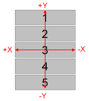
The mxy command is used to offset the telescope and change the position of targets within the IFU FOV. The syntax ismxy x ywhere x and y are expressed in arcsec. Moves in x move the target within the slitlets, while moves in y move the targets into the adjacent slitlets, as depicted in the following diagram and table.
|
| Apparent directions of motion of the target when using the mxy command relative to the IFU field of view. |
| Direction | Effect | Plot |
|---|---|---|
| -x | Shift target to the right within the slitlets |  |
| +x | Shift target to the left within the slitlets |  |
| -y | Shift targets toward the right slitlet |  |
| +y | Shift targets toward the left slitlet |  |
Sky Orientation
The following figures depict the approximate (give or take about 10°) orientation of the IFU slitlets at various ESI position angles. North is up and east is to the left in these diagrams.
| 0° | 90° | 180° | 270° |
|---|---|---|---|
 |
 |
 |
 |
Sky subtraction
Sky subtraction techniques with the IFU will depend on the nature of the target.- Compact targets. For targets which are very compact, it may be possible to perform sky subtraction in the customary manner using the light at the ends of the slit to define the sky background. However, given the short (4.0 arcsec) lengths of the slitlets, few targets will be amenable to this approach.
- Diffuse targets. IFU targets will generally fill most of the IFU field-of-view. In this case, the best approach for removing sky background will be to acquire an off-target image of “blank” sky, scale it appropriately to account for the exposure time difference, between the on- and off-target images, and subtract the two.
Acknowledgements
The ESI IFU was designed and built at UCO/Lick under the direction of Andrew Sheinis and is described a 2003 paper published in PASP. ESI observers making use of this device are requested to reference this paper in their publications.Send questions or comments to:ESI Support