


The guider concept was originally suggested by Sandy Faber. A curved mirror just beyond the outer edge of the upper (slit) wheel directs light to a pickoff mirror above and then into a Canon lens that feeds a shuttered Photometrics CCD camera. Light backscattered from part of the slitmask falls within the field of view of the guide camera. Both the offset guider field and the slit field show some vignetting.
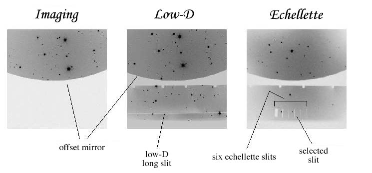
The figure below shows guider images from each of the three modes. The pixel scale is 0.223 arcsec/pixel, for a total field of 3.8 x 3.8 arcmin. In imaging mode, with the top wheel in the open position, only the curved mirror reflects light into the guider. When a slit or the echelle slitmask is in place, the guiding field is larger and it is possible in near-real time to position objects with respect to the slit. Generally the OA will handle this operation.
If you are using the IFU, the reflective surface of the IFU guide field is offset in focus from the offset guide field. With the IFU you will focus on the IFU guide field and guide off stars in that field.
To view the guider field the OA must have their guider software up and running. The observer then runs an “eavesdrop” of the OA's display. Select “Guider Eavesdrop” from the desktop menu. When you shut down the eavesdrop, remember to select “Guider Eavesdrop Stop” from the desktop menu, rather than simply quitting the window from the title bar. The menu item will also kill a second, hidden process. The normal ESI shutdown script will automatically clean up both processes.
The eavesdrop display has a small number of features. With the cursor on a pixel the (x,y) position and intensity in that pixel is displayed at the upper left. Note that the intensity value is only displayed (or at least valid) when the image binning is the default (currently 4x4). Circles can be used to mark objects or positions on the image. Click the middle mouse button on the desired pixel. Multiple circles can be displayed. To remove a single circle, click the right mouse button within 2 pixels of the circle center. To delete all circles push the “d” key on the keyboard while the cursor is in the eavesdrop window. Note that these changes are only made during full-frame readouts. While guiding these may be relatively rare, or even turned off completely.
Typing “b” (big) or “l” (large) on the keyboard with the cursor in the eavesdrop window will enlarge the image to its full 1024 x 1024 pixels. Typing “s” (small) returns it to its default 512 x 512. (Again the changes only take place during a full frame readout.) At any time you can resize the window to a smaller size. This activates scroll bars which let you access the entire image.
More details are available on the Web.
A set of six filters are located in the TV camera's filter wheel, as well as a lens. There is a set of BVRI filters as well as a neutral density (ND-1) filter and a clear piece of glass. The BVRI and clear filters were designed to be parfocal, but are actually not. The lens provides an out-of-focus image in order to do knife-edge focusing with one of the wide slits.
Each filter has a different focus, and these are defined by named focus positions of the form “Ifocus” or “Bfocus.” Unfortunately, these named TV focus positions are not accessible via the TV panel on the GUI. They are, however, in standard setups of the form “TV_I” or “TV_B.” It is probably easiest to select a new filter by reading in the appropriate named setup file.
The table below shows the positions and focus values for the filters. (It also shows the focus value for the IFU guide field.) Note that “Clear” is the normal position, with an empty filter wheel position and using the “Nominal” focus position. Note that the range of the focus stage is from -2400 to 2400.
Table 7.1. ESI TV Filters and Focus Positions
Position (TVFILORD) |
Name (TVFILNAM) |
Raw position (TVFILRAW) |
Focus name (TVFOCNAM) |
Focus (TVFOCRAW) |
|---|---|---|---|---|
1 |
ND_1 |
13800 |
ND1focus |
-1870 |
2 |
Glass |
28800 |
||
3 |
I |
43800 |
Ifocus |
-2300 |
4 |
V |
58800 |
Vfocus |
-2190 |
5 |
R |
73800 |
Rfocus |
-2200 |
| 6 |
Clear |
88800 |
Nominal |
-1450 |
7 |
Pupil_imager |
103800 |
na |
|
8 |
B |
118800 |
Bfocus |
-2245 |
na |
na |
na |
IFU |
-1900 |
There are four “pointing origins” (POs) defined for ESI. “REF” corresponds to the approximate center of the offset guider field [(x,y) = (512,256) on the image]. This is the usual acquisition position. Acquisition is usually done in either 2x2 binning or 4x4 binning. Centering and guiding are done in small, 1x1-binned subarrays centered on the object. The “ESI” PO refers to the center of both echellette and low-D slits. “Imaging” refers to the center of the facility filters, and is off the guider image to the lower right. The “EllisR” pointing origin is specific to the full-field R filter of the same name.
The OA will normally acquire your target position, and either identify the target themselves or have the observer help with the ID. They next center the target onto the REF PO, then send it to the relevant science PO (ESI, Imaging, or EllisR). It is important to understand the PO that you are using, and make sure that the OA sends the target to that PO. The current PO is found in the lower right corner of FACSUM. It is particularly important to distinguish between different imaging POs.
To better center a target on a slit, the OA may switch to 1x1 binning and enlarge his/her display to see individual pixels. It is not necessary for the observer to do this. A guide star is then selected, either on the slit or in the offset field. As mentioned, guiding is always done in 1x1 binning. The shutter is not used, nor is an erase cycle used while guiding. This very occasionally leads to vertical stripes, when a bright star lies above or below the guide box and the guide box reads out across the position of the star.
The OA can also save guider frames to disk. Tell them what binning you want. Due to relatively unsophisticated contrast control of the guider display, for some objects it is necessary to save a guider frame to disk and look at it in some other image processing package. The guider images will be written as “cam####.fits” (each # representing a digit) in a directory of the form “/s/nightly2/yy/mm/dd”, where “yy” is the last two digits of the year, “mm” is the month (no leading zeroes), and “dd” is the day (again no leading zeroes). This refers to the UT date, not the local date. For example, the fifth camera frame saved on the night of 25 July 2003 UT would be /s/nightly2/03/07/25/cam0004.fits. (Image numbers start with 0.)