Contents
Background
The LVMslits (Long Variable Multislit)
slitmask is a commonly-used DEIMOS mask which features several
longslits of varying width on a shiny surface, thus improving
the visibility of faint targets in the vicinity of the slit. By
offering numerous slit width options this mask can replace
several longslit masks, allowing room for more observer masks
while retaining the ability to use the apprpriate slit width for
the current observing conditions and target.
Since the shiny aluminum material is too floppy to work well
as DEIMOS mask materials, the slits are milled into a small
piece of reflective aluminum which is bonded to a normal
(non-shiny) DEIMOS slitmask. This document describes the
multistep procedure developed by Marc Kassis for generating
such masks.
Design Procedure
Note that the following steps are only required if the relevant
records have been removed from the slitmask database. If the
records described below still exist, you
can skip to the Milling Procedure.
DSIMULATOR Input Files
Three files are requried for manufacture the LVMslits
mask. Below are three coordinate files that were used to create
the masks.
longslits.in
This file contains the design information for the actual
longslits. Each is 20 arcsec long and the width varies from 0.7
to 1.5 arcsec.
CENTER    00:00:00.0  00:00:00.0 2000.0
slit0.7   00:00:00.0  00:01:00.0 2000.0 0.0 V 1 1 1 0 10.0 10.0
slit0.8   00:00:00.0  00:01:25.0 2000.0 0.0 V 1 1 1 0 10.0 10.0
slit1.0   00:00:00.0  00:01:50.0 2000.0 0.0 V 1 1 1 0 10.0 10.0
slit1.2   00:00:00.0  00:02:15.0 2000.0 0.0 V 1 1 1 0 10.0 10.0
slit1.5   00:00:00.0  00:02:40.0 2000.0 0.0 V 1 1 1 0 10.0 10.0
longslitcutout.in
This file describes a pattern which is used to cut out a chunk
of the shiny material into which the slits are milled.
CENTER    00:00:00.0  00:00:00.0 2000.0
slit1.0   00:00:01.6  00:01:50.0 2000.0 0.0 V 1 1 1 0 110.0 110.0
longslitgap.in
This file describes the cutout which is made in the normal
DEIMOS mask in order to allow the slits to see through the mask.
CENTER    00:00:00.0  00:00:00.0 2000.0
slit1.0   00:00:00.0  00:01:50.0 2000.0 0.0 V 1 1 1 0 100.0 100.0
Running DSIMULATOR
Because the DSIMULATOR package as of 11 April 2008 does not
support variable width slits, one must create five FITS mask
design files (MDF) with slit widths of 0.7, 0.8, 1.0, 1.25, and
1.5 and then cut/paste appropriate lines from each file to create
a master MDF file for ingestion into the slitmask database. All
the slits have lengths of 20 arcsec defined in the input files
(*.in) but the true slitwidth is controlled by
editing the slit width parameter in the DSIMULATOR
parameter set in IRAF.
- Configure DSIMULATOR paramters as follows:
      objfile = "longslits.in"  input file of targets
       output = "longslits.out" output list selected/non-selected
          mdf = "longslits.fits" Mask Design File (FITS)
  zoom_factor = 0.              [zoom_factor]
    (plotfile = "")             (opt) plotfile
         (ra0 = 0.)             Initial RA of field (hr)
        (dec0 = 0.)             Initial Dec of field (deg)
         (PA0 = 0.)             Initial PA of field (deg)
     (equinox = 2000.)          Equinox of coordinates
         (ha0 = 0.)             Initial Hour Angle (hr)
    (min_slit = 10.)            Minimum slit length (arcsec)
    (sep_slit = 0.35)           Separation between slits (arcsec)
  (slit_width = 1.)             Width of slit (arcsec)
      (box_sz = 4.)             Alignment box size (arcsec)
        (blue = 5000.)          Shortest wavelength of interest
         (red = 6000.)          Longest wavelength of interest
    (proj_len = no)             Project slit length to preserve in spatial dire
  (no_overlap = no)             Adjust slit lengths to avoid overlap? (YES)
  (std_format = yes)            Is input standard text format?
  (lambda_cen = 5000.)          wavelength for refraction
        (temp = 0.)             Air temp (C)
    (pressure = 615.)           Air pressure (millibars==hPa)
      (maskid = "Longslit with Variable Slith Width") Full Name of Mask
     (guiname = "LVMslits")     Name of Mask for GUI (6 char or less)
     (dateobs = "2100-01-01")   Date of intended use (YYYY-MM-DD)
      (author = "Gregory D Wirth <wirth@keck.hawaii.edu>") Designer of Mask (na
    (observer = "Gregory D Wirth <wirth@keck.hawaii.edu>") Observer (name
     (project = "Engineering")  Project name
       (coord = "")             graphics cursor input
       (flpar = no)             flush pfile on assign?
        (mode = "ql")
- Run DSIMULATOR once for each desired slit width,
creating a new mask design file on each iteration:
dsim mdf=lvm07.fits slit_width=0.7 mode=h
dsim mdf=lvm08.fits slit_width=0.8 mode=h
dsim mdf=lvm10.fits slit_width=1.0 mode=h
dsim mdf=lvm12.fits slit_width=1.2 mode=h
dsim mdf=lvm15.fits slit_width=1.5 mode=h
- Create a master MDF file by copying one of the
existing MDF files:
cp lvm07.fits LVMslits.fits
- Modify the master MDF file appropriately.
- Use the fv (FITS Viewer) utility to
modify the files:
fv LVMslits.fits
- Open extension 4 (DesiSlits) and
modify the slitWid field for each slit to
conform to actual.
- Open extension 7 (BluSlits) and modify
the fields as follows:
- For bslitID=0, make no changes
(since these data are for the 0.7 arcsec longslit,
and this file was duplicated from the
lvm07.fits file, these numbers are
already correct for the 0.7 arcsec longslit).
- For bslitID=1 (0.8 arcsec slit),
copy the values from the corresponding line in the
lvm08.fits file.
- For bslitID=2 (1.0 arcsec slit)),
copy the values from the corresponding line in the
lvm10.fits file.
- For bslitID=3 (1.2 arcsec slit)),
copy the values from the corresponding line in the
lvm12.fits file.
- For bslitID=4 (1.5 arcsec slit)),
copy the values from the corresponding line in the
lvm15.fits file.
In each case, the only numbers that will change are
the slitY values. Save the changes to the
LVMslits.fits file.
Submitting files for milling
You need to submit three files to the slitmask database for
milling. These files are:
- LVMslits.fits
- master slit file
- longslitcutout.fits
- cutout with width set in dsim to 120 arcsec
- longslitgap.fits
- 100 arsec long with width set in dsim to five arcsec
These files can be found in the directory
~dmoseng/slitmasks/LVMslits at HQ.
Milling Procedure
Materials required
- 1 LRIS mask blank (non-standard shiny stock) into which
the slits will be milled.
- 1 standard DEIMOS mask blank to which the shiny plate
will be affixed.
- 3M
Adhesive Transfer Tape Scotch #465, 1/2" Wide × 60 Yards
Long (McMaster Carr Part 7628A41 or here), for bonding the two pieces of sheet metal together.
- Lint-free optical tissue (Kimwipe)
- Ruler (for measuring line on mask)
- Exacto knife (for marking line on mask)
- Scissors (for cutting double-sided adhesive tape)
- 1 floppy disc with the 3 mill files mentioned below stored
Mill Files Required
| Name |
DesID |
BluID |
MillSeq |
Description |
| Longs1 |
5741 |
5727 |
EQ |
Small cutout around slits |
| Longs1 |
5743 |
5729 |
ES |
Shiny slit plate |
| LVMslits |
5751 |
5735 |
EY |
Series of short longslits |
Procedure
The order of operations is as follows:
- Mill LVMslits. Mill LVMslits
(MillSeq=EY) into normal DEIMOS slitmask stock
per standard procedure. Although these slits will be
excised in the following steps, we do this first so that the
proper name is milled into the mask stock. Leave the mask
in the mill for the following step.
- Create slit cutout. In this same mask, run mill
program EQ to remove the area around the slits.
Be sure to halt the mill as soon as the cutout has been
completed; do not allow the program to complete, since
this would obliterate the lettering created in the previous
step. The cutout should be perfectly centered on the series
of slits milled in the previous step.
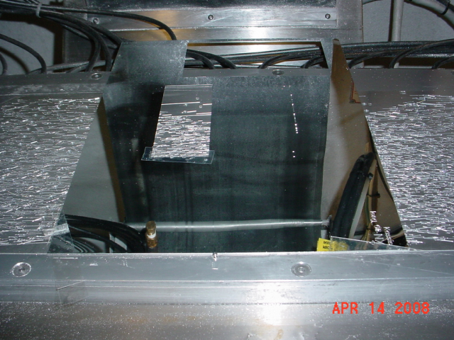
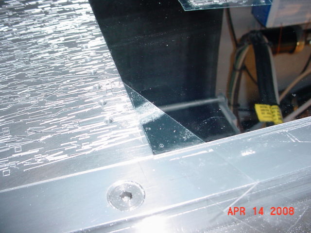
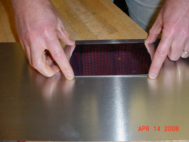
- Set up for slit plate. Remove milled
LVMslits mask from mill. Note location of slits.
Insert a piece of shiny LRIS stock at the location of the
slits, making sure that it is flush to the near side of the
slitmask boundary as shown below.
- Secure shiny stock. Affix mask in place with
adhesive tape to ensure that it does not move.
- Create slit plate. Run mill program
ES to cut out the plate of appropriate size in
the shiny stock. Again, halt the program as soon as the
plate has been completed. Remove the rectangular piece of
shiny stock from the mill.
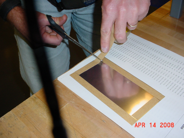
- Prepare slit plate. Affix double-sided 3M
adhesive tape to all edges of the rectangular stock, cutting
the material with scissors and burnishing the tape with
fingernail or other material to ensure good adhesion. Then
peel off the back side of the tape to expose the adhesive.
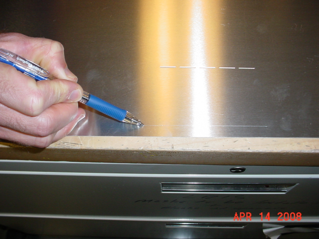
- Mark mask. Using a ruler and Exacto knife, draw
a line on the LVMslits mask at 1cm from the edge to mark the
intended location of the edge of the slit plate. If the
plate extends closer to the edge than 1cm, it will rub on
the slitmask form in DEIMOS and generate aluminum dust!
- Position slit plate. Carefully position the
shiny slit plate (tape-side down) centered horizontally over
the slit area on the LVMslits mask and at least 1cm from the
edge.
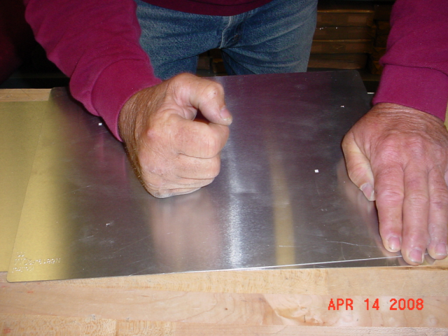
- Bond slit plate. Press the plate gently into
position. To affix it securely without marking up the shiny
stock, place a piece of optical tissue and a slitmask on top
of the plate and run first firmly across the area.
- Prepare to mill slits in plate. Remove the
spacer from the mill, and lay the LVMslits mask directly
atop the vacuum plate with no spacer (This is done
because the slitmask with plate is "double thick"). Secure
the mask in place with adhesive tape per standard procedure.
- Mill slits in plate. Re-run the LVMslits (EY)
program to mill the 5 slits into the shiny stock. Halt the
mill once the slits have been milled.
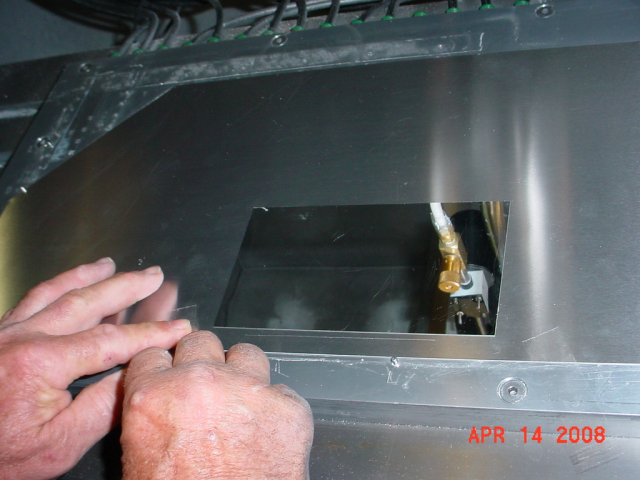
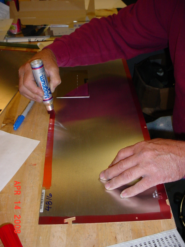
- Inspect and scan mask. Inspect mask for slit
quality and to verify that the newly-milled slits in the
shiny plate are centered on the cutout in the bottom
layer. If mask is acceptable, then apply red marker around
edge, affix barcode label, and scan mask.
- Stow mask. For storage, tape optical tissue over
the shiny stock to prevent scratches and store mask in
engineering mask collection.
See Also