
Director’s Introduction
Taft Armandroff, Director, WMKO

Welcome to the summer 2012 issue of the Keck Observers’ Newsletter. As our scientific community prepares for semester 2013A observing proposals, this Newsletter is designed to provide relevant and timely information. The past six months have been filled with exciting achievements in commissioning new observing capabilities and promising milestones towards other future systems that enable new types of observations.
MOSFIRE, Keck Observatory’s world-leading multi-object near-infrared spectrograph, has been undergoing commissioning during semester 2012A. The MOSFIRE instrument team and WMKO staff have made excellent progress, and MOSFIRE is performing very well. I am very pleased that over 50 nights will be devoted to MOSFIRE observing in semester 2012B. I expect that MOSFIRE’s unparalleled ability to obtain large samples of infrared spectra of faint sources will yield spectacular scientific results. Please see the MOSFIRE article in this issue of the Newsletter.
Our new Keck I laser guide star adaptive optics system has undergone final commissioning with the OSIRIS integral-field spectrograph (relocated from Keck II). It has now been used by several community astronomers for TAC-approved scientific observations, with positive performance and reliability. Again, please see the article in this issue of the Newsletter.
The Keck Cosmic Web Imager (KCWI) is an optical integral-field spectrograph for Keck II that is designed for high efficiency and excellent sky subtraction. The design phase of KCWI has been funded by the National Science Foundation (NSF) / National Optical Astronomy Observatory (NOAO) Telescope System Instrumentation Program (TSIP). We applied to TSIP for fabrication funding of KCWI in November 2011. I am pleased to report that NOAO awarded WMKO $2.9 million of TSIP funding toward KCWI fabrication. With this award, the NOAO observing community will gain access to 27 nights of Keck observing time distributed over semesters 2013A through 2014A. Unfortunately, NSF has terminated the TSIP program, so KCWI will be the final instrumentation development funded by TSIP. TSIP has benefited several other initiatives at WMKO (including OSIRIS, MOSFIRE, and NGAO) and other independent observatories. TSIP was endorsed strongly in the ASTRO2010 Decadal Survey report. I, the Keck Science Steering Committee and the CARA Board remain hopeful that NSF will establish a new TSIP-like program that builds on the successes of TSIP.
In the realm of Keck adaptive optics (AO), there have been several important developments. An initiative is underway to enable the determination of the point spread function (PSF) of each adaptive optics observation based on data from an atmospheric monitor and the AO system’s wavefront sensor. Its motivation is to eliminate reliance on asynchronous PSF calibration stars, leading to a reduction in random and systematic errors in astrometry, photometry, morphology and kinematics. I am pleased to report that WMKO was awarded $684,000 by the NSF’s Advanced Technologies and Instrumentation Program to support our PSF determination project.
An infrared tip-tilt sensor is being developed for the Keck I adaptive optics system, supported by NSF funding. This project successfully passed its Detailed Design Review in February 2012. The project has now transitioned to the full-scale development phase.
We have initiated a project to improve the scientific performance of the Keck II laser guide star (LGS) AO system by procuring and implementing a next-generation laser. The Keck II LGS AO system currently employs a 13 watt pulsed dye laser. The level of AO correction is limited by the laser power and especially by the low coupling efficiency of this laser to the sodium atoms. Narrowband continuous wave (CW) lasers have been demonstrated to have ~10 times the coupling efficiency of our dye laser. WMKO has been collaborating with the European Southern Observatory and a consortium of U.S. observatories to develop a 20 watt commercial CW laser. The resultant laser has been demonstrated in the lab by a consortium of two laser vendors, TOPTICA and MPBC, and has completed its final design. It is gratifying that two of the largest and most sophisticated private funders of scientific research have stepped up to support this initiative; the Gordon and Betty Moore Foundation has provided a grant of $2 million, and the W. M. Keck Foundation has contributed $1.5 million. This private support of our future development program is particularly important at this time when federal support of optical/infrared astronomy is diminishing.
Yale University has been participating in Keck Observatory via an agreement with Caltech since semester 2009A. Yale’s involvement in Keck Observatory has recently expanded. They have gained access to five additional Keck nights per year via an agreement with Keck Observatory that covers the period 2012 to 2016. Keck Observatory welcomes the greater engagement of the Yale astronomy and physics community.
The annual Keck Science Meeting, featuring scientific results from the Keck Telescopes, will be held at the University of California San Diego (UCSD) on September 20 and 21, 2012. The Scientific Organizing Committee is led by Adam Burgasser (UCSD), and the Local Organizing Committee by Alison Coil (UCSD). The meeting venue is the Institute of the Americas at UCSD. Please see the meeting web site for registration and other information. I anticipate another year of strong and diverse participation from the Keck Observatory science community and great talks revealing exciting new scientific results.
In closing, I would like to recognize some frequent users of Keck Observatory who have received prestigious awards over the past six months. David Jewitt (UCLA) and Jane Luu (MIT) were recognized with the Shaw Prize in Astronomy for 2012 for their “discovery and characterization of trans-Neptunian bodies.” Drs. Jewitt and Luu and Mike Brown (Caltech) were awarded the Kavli Prize in Astrophysics “for discovering and characterizing the Kuiper Belt and its largest members, work that led to a major advance in the understanding of the history of our planetary system.” Keck Observatory has played a significant role in the characterization of these outer Solar System objects. On behalf of the entire team at Keck Observatory, congratulations to Drs. Jewitt, Luu, and Brown for this recognition of their pioneering work on the outer Solar System! ✶
MOSFIRE Goes On-Sky and Fulfills High Hopes
Ian McLean, Professor of Astronomy & Astrophysics, UCLA
Chuck Steidel, Lee A. DuBridge Professor of Astronomy,
Caltech
WMKO’s newest instrument, the Multi-Object Spectrograph for Infrared Exploration (MOSFIRE), achieved “first light” on Keck I on April 4–5, 2012. Although the weather did not fully cooperate (both nights being largely overcast), commissioning got off to a great start with all systems on MOSFIRE working remarkably well. Since then, the commissioning team has put MOSFIRE through its paces and characterized its on-sky performance. The instrument is meeting all requirements on throughput, sensitivity, and stability, and first science results exceed expectations. The cryogenic configurable slit unit (CSU) is working well and the Slitmask Alignment Tool (SAT) has proven efficient and reliable. At the time of writing, all commissioning runs are complete and the instrument web page is being updated to reflect the most recent developments. The Observatory has scheduled MOSFIRE for shared-risk observing in semester 2012B, and we anticipate it will be available for regular use by the Keck observing community starting in 2013A.
We were pleased to verify that the instrument focus is every bit as stable as anticipated. MOSFIRE’s optics were designed to be achromatic, but a detector focus mechanism was included in the instrument to allow us to adjust the focus if required. During laboratory testing with a pinhole mask in the focal plane instead of the CSU, we demonstrated that the image quality was excellent and that a single focus was appropriate for all wavelengths and all points within the field of view. Our best estimate of the rms image diameter in imaging mode was <0.18″ (~1 pixel) averaged over all bands, with no refocus. The requirement was <0.25″, so we were anxious to see what the image quality would be on the telescope under good seeing conditions. Figure 1 shows that we were not disappointed; MOSFIRE’s optics are truly superb.

|
Our astrometric characterization of MOSFIRE indicates that the pixel scale is essentially constant across the entire instrument field of view, with a measured plate scale of 0.1798″ pixel–1. All MOSFIRE image headers are populated with world coordinate system information that provides immediate access to orientation, handedness, and astrometry. The same globular cluster stars shown in Figure 1 were used to map the distortion and derive an astrometric solution for the CCD guide camera located 6.7′ off axis. The guider pixel scale is variable across the field of view (distortion ranges from ~1% in the center half of the field to almost 10% in the corners), but applying our derived astrometric solution converts the coordinates to a rectilinear grid accurate to ~0.02″ based on HST astrometry. Once the Observatory updates its MAGIQ guider software to incorporate this guider plate solution, we anticipate that accurate telescope offsets will be possible over the entire 2.8′×2.8′ guider field. Guiding appears to be very good: once the observer has used the SAT software to center the MOSFIRE slits on the science targets, the offset guider does an excellent job of holding objects in 0.7″ slits for many hours.
MOSFIRE’s optical stability is also outstanding. The instrument is equipped with a flexure compensation system that keeps images or spectra fixed with respect to the detector to within <0.1 pixels (<0.018″) rms at all elevations and orientations; in fact, we found that spectra acquired using the same slit mask on separate runs a month apart could be reduced using the same calibration data, indicating that in addition to the image stability, both the CSU and the grating positioning are highly repeatable.
On-sky testing demonstrates that MOSFIRE’s throughput is as high as hoped. At pre-ship review, we estimated the throughput of MOSFIRE alone; i.e., the throughput from slit to detector without accounting for the telescope optics or atmospheric transmission. The predicted average throughput values for the Y, J, H and K spectroscopy bands were 30.8%, 32.5%, 36.1% and 35.0%, respectively. These estimates included glass transmission, grating efficiency, and anti-reflection coating on glass and mirrors, as well as the detector quantum efficiency. As shown in Figure 2, the agreement between the predicted and measured “on-sky” throughput is remarkably good in all of these bands.

|
Another goal of commissioning was to measure the sky background for imaging and spectroscopy modes. All observations were carried out during full moon, which measurably increases the sky background at the shortest wavelengths. The data tables below display the measured sky brightness (units of magnitudes per square arcsecond) in both the Vega and AB systems for the imaging (Table 1) and spectroscopic (Table 2) modes. The average sky intensity (in units of electrons per spatial pixel per second between the OH lines) appears in column 4 of Table 2. The low count rates for the sky background reflect one of the major goals in the design of MOSFIRE: to take advantage of the very low terrestrial background for spectral regions away from strong OH emission lines. Note (for example) that in H band the background reduction factor is ~2.7 magnitudes in comparison to the broadband background (and a factor of ~500 times lower than the brightest OH line in H band). All of these numbers are consistent with our expectations and assumptions.
| Passband | Sky Brightness [mag/arcsec2] |
|
|---|---|---|
| Vega | AB | |
| Y | 17.37–17.50 | 18.02–18.15 |
| J | 15.49–15.87 | 16.39–16.77 |
| H | 13.59–13.89 | 14.99–15.29 |
| Ks | 13.68–14.25 | 15.54–16.11 |
MOSFIRE’s outstanding sensitivity for imaging and spectroscopy also depends on the high-QE, low-noise performance of its Teledyne HAWAII2RG detector. Our goal was to achieve detector dark current under 0.01 e– s–1 px–1, and we expected (with the aid of many multiple non-destructive reads, also known as multiple correlated double sampling [MCDS] or “Fowler sampling”) that the effective read noise could be reduced to ~3 e– rms. In the lab, long dark exposures measured a value of under 0.008 e– s–1 px–1 for the average dark current, and a sequence of noise measurements using increasing numbers of non-destructive reads demonstrated that 3.2 e– rms was achievable with 64 reads, while 16 reads was sufficient to get below 6 e– rms. Operating in single-read mode (also known as “correlated double sampling” or CDS), MOSFIRE achieved 17.2 e– rms in the lab. Figure 3 shows the results of performing the same experiment on the telescope. The observatory environment is electrically noisier. In CDS mode the measured read noise is 23.2 e– rms, but 16, 32 and 64 reads essentially yield noise within ~10% of lab values. This performance ensures that MOSFIRE becomes background-limited — even in the darkest sky regions between OH lines — in only a few minutes for all four spectroscopic bands, and that dark current is always entirely negligible.
| Spectral Regime | Sky Brightness [mag/arcsec2] |
Observed Background [e– s–1 px–1] |
|
|---|---|---|---|
| Vega | AB | ||
| Y | 18.73 | 19.38 | 0.34 |
| J | 18.34 | 19.24 | 0.30 |
| H | 17.32 | 18.72 | 0.57 |
| K | 16.35 | 18.21 | 0.39 (λ < 2.2 µm) |
| 14.05 | 15.91 | 8.0 (2.35 µm < λ < 2.41 µm) | |

|
To allow prospective MOSFIRE observers to determine the quality of spectra they can obtain, Gwen Rudie of Caltech has written a spectroscopic exposure-time calculator called XTCalc (see Figure 4) which incorporates the MOSFIRE commissioning observations and calibrations. Observers can run the XTCalc GUI from any MOSFIRE observing account at WMKO, or can download the latest software and documentation from Caltech.

|
To illustrate the capabilities of MOSFIRE in spectroscopic mode, we observed a set of high-redshift galaxies in K band in a search for H-alpha emission. After the mask has been aligned, typical observations will involve nodding the telescope in the direction along the slit to place each target at two or more spatial positions. In this case, we acquired a series of 180 s integrations which employed a “mask nod” pattern of ±1.5″, leading to a 3″ separation between the “A” and “B” positions. We performed a crude background subtraction by stacking all of the exposures taken at the “A” position, and all those at the “B” position, and simply subtracting one set from the other (we refer to this as an “interleaved difference image”). Figure 5 shows the result for such an interleaved difference in which there were 5×180 s integrations at each position (i.e., a total of 1800 s on-source).

|
To help observers get the most out of their MOSFIRE data, the instrument team has written and released a MOSFIRE Data Reduction Pipeline (DRP) which has undergone substantial testing and revision during commissioning. The MOSFIRE DRP is designed to take a sequence of spectroscopic exposures (which will typically be obtained using 2 or more nod positions in an alternating pattern) and automatically produce flat-field corrected, background-subtracted, wavelength-calibrated, and rectified 2D spectra, along with products useful for quantifying the data quality. Figure 6 shows the mask observations from Figure 5 after processing via the DRP.

|
We should also point out that MOSFIRE is Keck’s first wide-field IR imaging camera. Figure 7 illustrates deep imaging in the Ks band using a rectangular dither pattern to derive a sky flat. The limiting magnitude here is Ks=23.5 (Vega; S/N~10 in a 0.5″ aperture) based on one hour total integration time. The image quality in the stacked image is FWHM=0.56″.
|
To summarize, MOSFIRE is a powerful instrument. It was technically challenging to build and many people contributed to its ultimate success. The co-PIs would like to take this opportunity to thank each and every team member for their participation, and to acknowledge the support of our colleagues at WMKO as well as our sponsors, the NSF Telescope System Instrumentation Program (TSIP) and Gordon and Betty Moore. Good observing! ✶
SHARP Images of Gravitational Lenses Reveal Invisible Galaxies
Chris Fassnacht, Professor of Physics, UC Davis
One of the big questions in extragalactic astronomy is how galaxies formed. The cold dark matter (CDM) paradigm does an excellent job in predicting the observed properties of structure in the Universe on large scales. However, on galactic scales discrepancies start to appear. One of the most prominent is the so-called “missing satellites” problem. Numerical simulations of galaxy formation produce large numbers of satellites (also referred to as substructure or subhalos) that are associated with each galaxy-sized halo. However, observations of the Milky Way detect many fewer satellites than predicted, especially at lower masses. This is in spite of heroic efforts to find and measure the properties of these low-surface-brightness objects in large sky surveys. Among the proposed explanations for this discrepancy are:
- the satellites are there, but they are not detected because they are extraordinarily faint or perhaps composed purely of dark matter;
- there is something wrong with the CDM paradigm, at least on sub-galactic scales; or,
- the Milky Way is an outlier.
To understand how this approach works, consider an analogy: looking at an image of a light source taken through a piece of glass. If the piece of glass is smoothly varying in thickness, then the light source will appear to be distorted. Furthermore, if there are small-scale imperfections in the piece of glass, the image of the light source will be perturbed on small scales. This is the situation that we observe in the case of strong gravitational lensing of a distant galaxy. The light from that galaxy passes through the potential well of a foreground (lensing) galaxy and is distorted, in some cases forming long arcs or even a complete ring. The presence of substructure in the lensing galaxy will perturb the ring, and the scale of the perturbations will depend only on the mass of the subhalo and not on whether the halo is luminous or not. Thus, with lensing we have the capability of detecting even purely dark satellites of the lensing galaxy. We call this technique “gravitational imaging.”
Because the angular scale of the perturbations depends on the mass of the substructure, it is beneficial to obtain the highest possible angular resolution in the observations. By pushing to smaller angular scales, we are able to study the low masses where the discrepancies between the simulations and Milky Way observations start to become significant. To this end, we have started the Strong-lensing High Angular Resolution Program (SHARP), a small collaboration consisting of Chris Fassnacht (UC Davis), Simona Vegetti (MIT), Matt Auger (Cambridge), Leon Koopmans (Kapteyn), Dave Lagattuta (Swinburne), and John McKean (ASTRON). By using the adaptive optics (AO) capabilities of Keck and imaging with NIRC2, we have obtained images of a sample of lens systems that have higher angular resolution than Hubble Space Telescope (HST) images at similar wavelengths (see Figure 8). Thus, for objects that are red, either because they are at high redshift or because of extinction, the Keck AO data provide better constraints on substructure than the HST images.

|
Our program has recently had an impressive proof of concept, through the detection of a substructure in the B1938+666 system (right-most column in Figure 8). The lensing analysis revealed a substructure with a mass of roughly 2×10⁸ solar masses, detected in NIRC2 data obtained in the Kp and H bands, as well as HST/NICMOS imaging in F160W (H band). For a more direct comparison with the Milky Way satellites, this corresponds to a mass within 300 pc of 7×10⁷ solar masses. The substructure was detected in all three datasets, but with the highest significance in the Kp AO data (a 12σ detection). The galaxy being lensed is at high redshift, and so the ring only becomes visible in the near-infrared where the Keck AO imaging is significantly sharper than HST imaging. These results for the B1938+666 system, reported in a Nature paper by Vegetti et al., are only the second case in which substructure in a galaxy-scale lens has been detected via the gravitational imaging technique. The other detection was made with HST, and was for a substructure that was nearly 20 times more massive than the one in the B1938+666 system. The goal of SHARP is to obtain similar mass sensitivities on a sample of 20 lens systems, at which point we can start to obtain meaningful constraints on the properties of substructure in massive galaxies and thus provide direct tests of the predictions made by simulations of galaxy formation. ✶
Keck I LGS AO System Enters Shared-Risk Science Phase
Randy Campbell, AO Operations Manager, WMKO
We are pleased to announce that as of May 2012, the Keck I Laser Guide Star Adaptive Optics (LGS AO) system has entered the shared-risk science phase. OSIRIS, an integral-field spectrometer and imager for AO, moved from Keck II to Keck I in early 2012 to be the first dedicated science instrument used with the new system. The integration of OSIRIS and Keck I LGS AO is the culmination of an intensive effort by several teams of dedicated Keck personnel. A number of observers have already used the system for shared-risk science and their feedback has been mostly positive. We held an internal operational readiness review for the system in July 2012 that marked the transition of the system to operations. The review was successful, although the system will continue to operate in shared-risk mode during the transition phase while a few remaining issues are resolved.
The Keck I LGS AO system is comprised of several components including the laser, beam transport and projection, safety system, AO bench, and the science instrument OSIRIS. The Free Space Transport (FST) system was the last of these subsystems to be developed (see the article from the Winter 2011 issue) and its recent completion has removed the final barrier to shared-risk science observing.
Although the full characterization of the system’s performance is ongoing, initial results demonstrate that the quality of the AO correction from the new Keck I system is comparable to its counterpart on Keck II. The system’s Strehl ratio, which characterizes the delivered image quality relative to the theoretical limit, has reached the 30%–40% range for bright stars observed on-axis. Although Keck I LGS AO observers may experience some near-term “teething pains” in the form of lower efficiencies and higher frequency of faults compared to Keck II’s more mature LGS AO system, please rest assured that Keck’s AO Development and AO Operations teams are working hard to refine the systems’s performance.

|
The solid-state laser by Lockheed Martin Coherent Technologies (LMCT) has typically been emitting 20–25 watts of yellow (589 nm) light tuned to excite sodium in the mesosphere at an altitude of 90 km. The resulting artificial star brightness has been on the order an equivalent V magnitude of 9–10 and the size typically ~1.6 arcsec in diameter. Laser reliability has been very good with negligible time lost to laser problems thus far during shared-risk science.
The FST system that redirects the emitted laser light from its origin on the Nasmyth platform to the center-launch telescope behind the Keck I f/15 secondary includes several tracking stages. Designing, assembling, and perfecting the servo control of the beam-steering mirrors has been challenging, but that system is now functioning well. The laser acquisition, tracking, offsetting, dithering, and laser focusing have performed adequately, although some fine tuning of some of the pointing models is ongoing. Of course, a significant amount of software was developed to control the FST and it is also performing satisfactorily. At the operator level, some new GUIs have been implemented while training and experience with these GUIs is ongoing.
The Keck I AO bench is essentially a duplicate of the successful Keck II system and is generally working well. There are a few subtle issues related to the different laser and transport systems in use on Keck I, however. For example, the Keck I system is more sensitive to sky background changes associated with cirrus clouds since the center-launched Rayleigh backscatter pattern is within the field of view of the wave-front sensor (WFS). The Keck II system is more tolerant of cirrus because its laser is side-launched and thus the near-field laser backscatter does not appear in the AO field of view. The changing background causes problems for the WFS, so more frequent sampling of the background is required, resulting in minor inefficiency in the best cases and rendering observing impossible in the worst cases. Mitigation techniques such as use of a field-limiting stop are being developed but, in general, observers should expect that system performance on Keck I will likely be significantly impacted by the presence of thin cirrus. As with all LGS programs, observers should prepare good natural guide star (NGS) backup program in case LGS observing is not possible.

|
OSIRIS is now mounted at the fixed AO focus of Keck I (see the article in the Winter 2012 Newsletter), meaning that it is no longer on a cart and cannot be exchanged for other instruments, as was the case when it was used with Keck II AO. A new mounting fixture was developed for this purpose. OSIRIS achieved “second light” on 2012 March 12 and has generally been performing very well since its relocation. There is one less mirror in the Keck I AO light path than on Keck II and thus the orientation of the detectors is flipped relative to the sky and the AO system. Modifications were made to the OSIRIS pipeline and imager software to render the correct handedness and orientation to the observer. Although most OSIRIS science programs employ the integral field spectrometer, we anticipate increased usage of the imaging mode on Keck I; thus, re-commissioning efforts have included optimizing the image quality with a phase retrieval technique (Van Dam 2004) and other improvements such as lowering the minimum readout time to 0.8 s. The imager filter wheel currently has a status read-back problem and this has rendered some of the high-level observing tools unusable for the imager. However, this is a relatively minor problem and work-around tools are available for those wishing to use the imager. The spectrometer is working normally and can still be controlled from the high-level observing tools.
Key members of the Keck I LGS team include Jason Chin, Jim Lyke, Olivier Martin, Joe Mastromarino, Doug Morrison, Chris Neyman, Pete Tucker, Ed Wetherell, and Peter Wizinowich. ✶
Astronomer-Friendly Software for “Goof-Proof” Slitmask Alignment
Gregory D. Wirth, Support Astronomer, WMKO
Marc Kassis, Support Astronomer, WMKO
Multi-object spectroscopy is a key capability at Keck, being used on most nights when LRIS, DEIMOS, or MOSFIRE is on the telescope. While the multiplexing capability offered by slitmask spectroscopy provides an enormous increase in observing efficiency, the process of aligning the slitmask with the on-sky targets can be complex, inefficient, and prone to error, often costing observers significant on-sky time. Inexperienced observing teams may not come prepared with adequate finder charts and often struggle to master the procedure. Even experienced observers are susceptible to errors in field identification that can waste precious sky time.
For some time we’ve intended to write software which could simplify and unify the slitmask alignment process across all of the Keck instruments supporting multi-slit spectroscopy. We are thus pleased to announce the release of the Slitmask Alignment Tool (SAT), an IDL-based GUI which will allow users of LRIS, DEIMOS, and MOSFIRE to complete mask alignment simply and efficiently. The SAT accomplishes rapid initial mask alignment, prevents field misidentification, accurately predicts alignment box image locations, corrects for flexure-induced image displacement, verifies the instrument and exposure configuration, and accommodates MOSFIRE-style trapezoidal alignment box shapes in addition to the usual rectangular boxes employed on LRIS and DEIMOS. The software is designed to lead observers through the slitmask alignment process and to coordinate image acquisition with instrument and telescope moves to maximize efficiencies. By simplifying the process to just a few mouse clicks, the SAT enables even novice observers to achieve robust, efficient, and accurate alignment of slitmasks on all three Keck instruments supporting multislit spectroscopy, saving substantial observing time.
A pair of figures conveys the essence of how the SAT works. The observer typically starts the mask alignment process by using the SAT’s Guider Coarse Align screen, shown in Figure 11 below, to complete a quick, rough alignment of the mask in order to put the alignment stars into their respective boxes on the slitmask. As the numbers in the figure indicate, completing this first phase of mask alignment requires just four mouse clicks:
- The observer uses the target droplist to select the target name, causing the tool to retrieve the DSS image corresponding to the guider field of view for a correctly-aligned mask, display it in the left pane, and mark the predicted locations of stars from the astrometric catalog.
- Clicking Grab Guider Image triggers the guider software to acquire and save a guider image of the field, which the SAT loads and displays on the right pane; it also marks the corresponding predicted guide star locations.
- Clicking the image of any one of the guide stars in the right pane causes the tool to adopt that location as the true location of the star and to compute the offset between the predicted and actual pixel position of the star.
- Clicking the Move Telescope button will offset the telescope by the appropriate amount to put the alignment star image at the desired location.

|
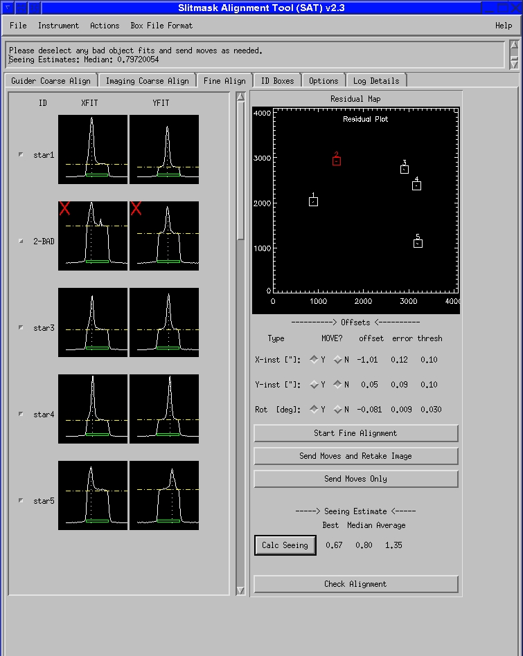
The alignment process continues on the Fine Align screen, depicted in Figure 12 below. The goal of the fine alignment process is to accurately center the alignment stars within their respective boxes on the slitmask. Completing this phase is nearly as painless as the coarse phase and typically proceeds as follows:
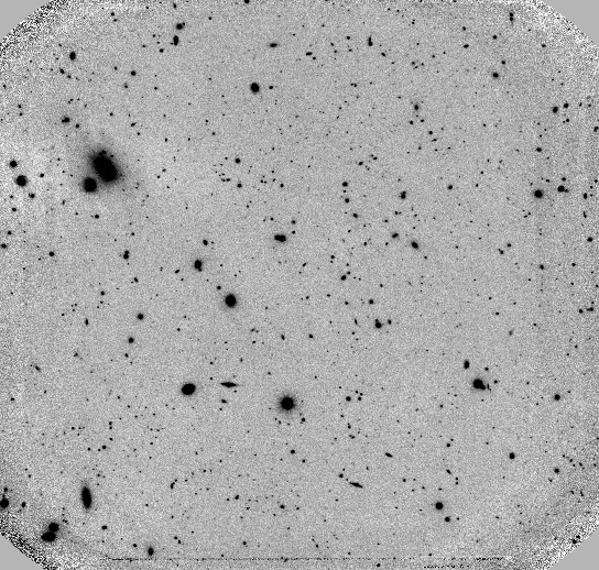
- The observer clicks the Star Fine Alignment button to initiate the process. The software triggers the instrument to acquire a direct image of the sky through the mask (reconfiguring the spectrograph for imaging as needed), reads in the resulting image, locates the alignment boxes, analyzes the star profiles within the boxes, derives the telescope and rotator moves required to optimize the centering, and displays the results.
- The user can reject one or more discrepant stars from the fit by clicking the small button to the left of the XFIT/YFIT graphs. The tool then recomputes the fit, excluding any rejected objects.
- The SAT determines whether to send any of the three possible moves (telescope X shift, telescope Y shift, or instrument rotation) based on the size of the move relative to an instrument-specific threshold. The user can choose to accept or override the recommendation of the tool.
- If moves are significant and another iteration of fine alignment is desired, the user clicks on Send Moves and Retake Image to apply the selected moves and initiate another alignment exposure. If moves are small enough that another iteration is not required, clicking Send Moves Only will apply the moves and complete the process. If moves are insignificant, no action is necessary.
|
We began testing the SAT on LRIS late in 2011, and once we solved some guider flexure problems we deployed SAT for routine use on LRIS early in 2012. Feedback from LRIS observers has been overwhelmingly positive, and an analysis of the time spent on mask alignment indicates that SAT is saving observers significant time on sky. SAT has been used on MOSFIRE since the first commissioning run, and we hope to deploy SAT on DEIMOS during the 2012B observing semester. Future improvements are planned to make it even more robust and efficient. Please feel free to ask your support astronomer for an SAT tutorial on your next observing run; we’d love to hear your suggestions for further enhancements! ✶
Slitmask Incentives: Do They Help Reduce Late Masks?
Robert W. Goodrich, Observing Support Manager, WMKO
Gregory D. Wirth, Support Astronomer, WMKO
LRIS and DEIMOS slitmask observers know that WMKO requires teams to submit their slitmask design files four weeks in advance of their observing run; this ensures us adequate time to mill your masks (and those of others) while also allowing us time to perform mill maintenance and to schedule our millwrights in the most efficient manner. Of course, when observers can claim valid scientific justification for having to submit late mask designs (recent discoveries, recently obtained target lists, astrometric solutions based on recent data, etc.), we are happy to grant formal extensions of one or more weeks. But there are fundamental limits to how many late masks we can process, and thus the need for a system to encourage teams to submit their masks well in advance of their runs.
We formalized this arrangement in 2006 when we published an “incentive schedule” designating late-mask fees we would charge to teams which failed to meet the four-week deadline. Our goal was not to create a source of income for the observatory, but simply to emphasize the importance to observatory operations of timely slitmask submission. Because most observing teams have been conscientious about getting slitmasks submitted on time, we have never collected a cent of late fees.
We cannot overemphasize the importance of good communication in this process. When late masks take us by surprise, we either run the risk of being unable to mill some requested masks (potentially compromising the science of those observing nights) or having to pull summit staff off of their scheduled tasks in order to perform emergency mask milling (thus preventing us from doing important work on the telescopes and instruments). However, when observing teams let us know when and how many late masks they will submit, we can plan accordingly to ensure that every team’s needs are satisfied with minimal disruption to our operations.
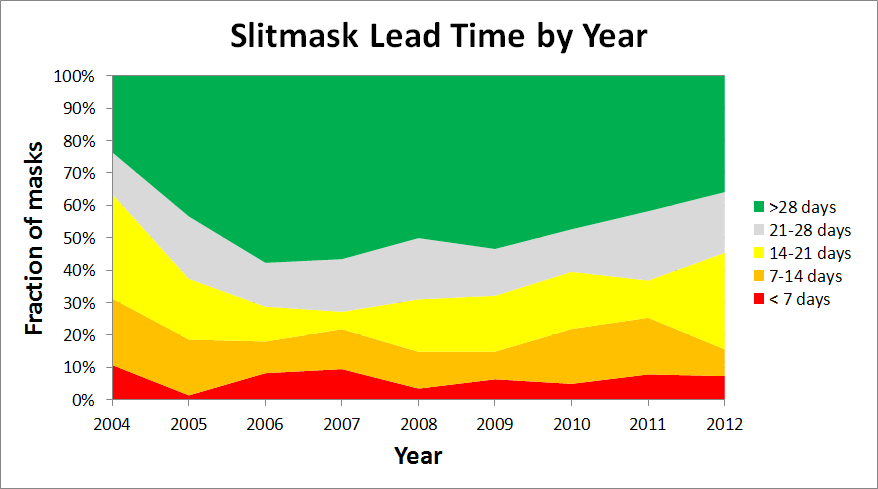
So how have observers been doing? In Figure 13 we show how the slitmask lead time (i.e., the number of days before the run when we receive the masks to mill) has varied from year to year since we began tracking slitmask statistics in 2004. In a perfect world in which all observers submitted their masks at least four weeks before the run, the graph would show solid green. In reality, we see that the fraction of masks received at least four weeks prior to the run (as indicated by the green area in the graph) was initially low (only 24% in 2004), increased markedly once the incentives were announced (peaking at 58% in 2006), and has been steadily decreasing ever since (down to 36% this year). Some of this increase in “late” masks is the understandable result of observers needing to obtain recent data from other telescopes to select their targets and design masks. Regardless of whether the increase in late masks is justified scientifically, the net result is that our summit staff is working with a somewhat smaller margin for error than before. Fortunately, the fraction of very late masks (indicated in red) has remained consistently low at under 10%. But clearly there is still room for improvement!
|
What can we, as a community, do to improve? On the observatory side, WMKO has implemented better slitmask tracking and notification systems. When you submit your instrument configuration request through our web form, you specify a list of slitmasks that you intend to use. Our software monitors this list and will send you e-mailed reminders of masks which have not yet been submitted. If you’ve been granted a formal extension to your slitmask deadlines, these reminder e-mails won’t be sent until the revised deadline expires.
There are still “holes” in the automated system, however. Until you submit your instrument configuration request, we have no way of knowing whether you’ll be using slitmasks, how many you plan to use, and whether the masks are already in our collection, are submitted and awaiting milling, or are not yet submitted (or designed!). If you submit an incomplete or inaccurate request (e.g., omitting masks you have not yet submitted, or listing them under a different name), the reminder system won’t be able to accurately determine which masks are outstanding.
What can you, the observers, do to help? The key to the entire process remains good communication. First of all, please try your best to submit your mask designs by the four-week deadline; you’ll eliminate the stress and worry of late masks and avoid receiving reminder e-mails from us. If you have a valid scientific justification to submit masks late, please let us know before the deadline passes. Even if you don’t have valid scientific justification, but you know that you’ll be submitting late slitmasks, please let us know! If you can provide us with an estimate of when we can expect your late mask designs to arrive, then we can schedule our millwrights to make sure they are ready to mill your masks once you’ve submitted your designs.
How important is this? Has anyone had masks not get milled because of lateness? In fact, yes! Furthermore, when observers have submitted multiple late requests we’ve sometimes had to scramble to decide which masks we could and could not mill. The dedicated summit crew has always done their utmost trying to make sure all masks get milled, but there are limits to what we can accomplish.
Remember, it’s your Keck observing time. Please continue to help us get the most out of it by submitting your masks on time, or by notifying us promptly when your masks will be late. ✶
Hundreds Flock to Keck to Watch Venus Cross the Sun
Greg Doppmann, Support Astronomer, WMKO
On 2012 June 5, more than 700 visitors showed up at Keck Headquarters in Waimea to experience a rare astronomical event: the transit of Venus. Most people were aware that this would be the last chance in their lifetimes to witness our nearest planetary neighbor sliding in front of the Sun, with the next occurrence not happening until 2117.

|

|
Perhaps less known to people today was the fundamental importance a Venus transit had to astronomy back in the eighteenth century. It was the first opportunity to measure accurately the absolute distance to the Sun and thereby establish the critical first rung in the cosmological distance ladder.
Over the next six and a half hours, an enthusiastic crowd lined up to view the transit through several solar telescopes set up at Keck headquarters. Keck’s own Larry O’Hanlon and Andrew Cooper streamed a live webcast from the Keck I control room which was projected on a large video screen in the Hualalai Learning Theater at our headquarters facility, providing our visitors an opportunity to hear an informative commentary and witness the event happening live from the summit of Mauna Kea. The Keck webcast was extremely popular, garnering over 87,000 unique views, reaching families and groups around the world. In short, the 2012 transit of Venus was the largest outreach activity hosted by Keck Observatory yet! ✶
Changing of the Guard Among the Instrument Masters
Robert W. Goodrich, Observing Support Manager, WMKO
At Keck we use the concept of “Instrument Masters.” Each facility instrument has a Support Astronomer (SA), with extensive knowledge of the instrument and extensive experience supporting it, designated as the Instrument Master. A second SA is designated as the Instrument Secondary Master, to provide backup and a small team to work together on each instrument. Of course, there may be other SAs who support observers on any given instrument as well. When there are problems or minor improvements to an instrument, “the buck stops” at the desk of that instrument’s Master.
On occasion, we pass this important responsibility on to a new Master, or inaugurate a new master for an incoming instrument. This month we are celebrating a number of such changes.
Support Astronomer Luca Rizzi, who joined us from UKIRT just over a year ago, has been named the new Instrument Master for LRIS, our workhorse optical spectrograph on Keck I. As one of our most popular and flexible instruments, LRIS requires a high level of expertise to support and Marc Kassis has been the LRIS Instrument Master for several years, seeing the instrument through some major upgrades such as the new red-side dewars, new MAGIQ guide cameras, and a new Slitmask Alignment Tool (described in a separate article). We thank Marc for his years of service as LRIS master and are confident that Luca will be a worthy successor.
Marc himself is the Instrument Master for the new MOSFIRE infrared instrument, also described in this Newsletter. He will have help from MOSFIRE's secondary master, Greg Wirth. Marc, Greg, and the other SAs are already guiding MOSFIRE through its transition to full operations in 2012.
NIRSPEC also has a new master: Support Astronomer Greg Doppmann, who started work at Keck last August after gaining instrument support experience at both Gemini and NOAO. Greg succeeds Jim Lyke, who has guided NIRSPEC through some challenging times, including developing an improved method for removing ice from the optical path, commissioning the very first MAGIQ guide camera, and working to fix problems with the near-IR SCAM guider. Greg takes over at a crucial time for NIRSPEC as it undergoes a delicate servicing mission to repair the SCAM guider, which has shown new but different problems. We thank Jim for his stewardship of NIRSPEC and appreciate Greg's willingness to step into the fray and lead the troubleshooting of this critical issue.
Mainland observing is not an instrument per se, but it is a very important aspect of observing at Keck, and Greg Wirth, together with a great deal of help from Bob Kibrick, in particular (as you can in the article following this), has been the WMKO champion of mainland observing. We owe a great deal to Greg and Bob for making mainland observing a smooth and trouble free experience, and Greg has been officially named as the Mainland Observing Master, with Jim Lyke as his Secondary.
These are exciting changes, and bring new insights and strengths to bear on our observer support. We can look forward to many more years of smooth science operations on all of our instruments, thanks to the dedication and hard work of all of the Instrument Masters. ✶
An Appreciation for Bob Kibrick, Who Worked Behind the Scenes to Improve Keck
Gregory D. Wirth, Support Astronomer, WMKO
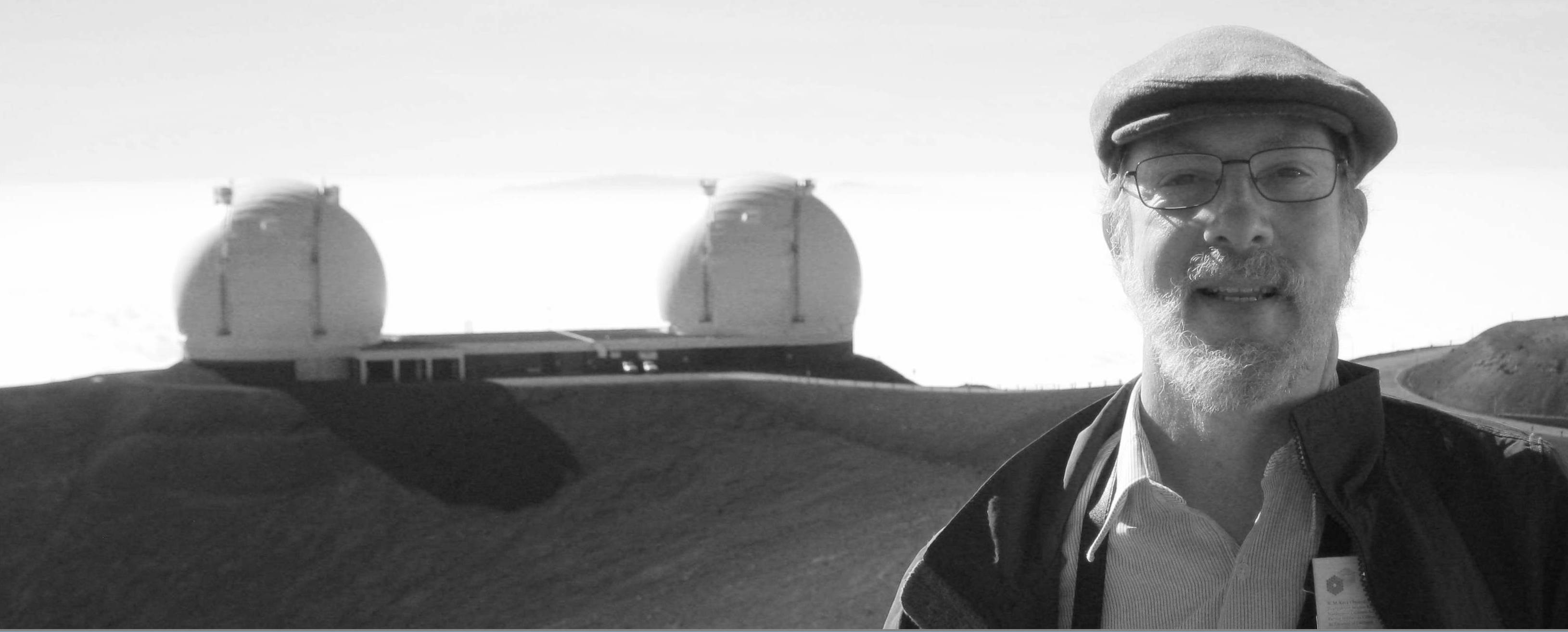
At the end of June, 2012, Robert I. Kibrick officially retired from his position as Research Astronomer after 36 years on the staff of UCO/Lick Observatory. Although Bob neither designed the Keck telescopes nor led an instrument team, his extraordinary efforts have done more to improve the observing experience at Keck than all but a select few.
Bob was a driving force behind the software team at UCO/Lick which contributed substantially to the success of HIRES, ESI, DEIMOS, and the new red dewar on LRIS. Experienced Keck observers will note that these are among our most reliable instruments, with a reputation for stable keyword servers and graphical user interfaces, plus rock-solid detector systems that can run (quite literally) for a year at a time without a single fault. This is no coincidence, as Bob’s tenacity led him and his talented colleagues in the Lick Scientific Programming Group to track down and fix the bugs which cause systems to crash.
|
Despite the fact that he had many responsibilities at Lick, Bob’s dedication to the Keck instruments he had worked on was legendary. Those among the Support Astronomer team who worked with Bob knew that if anything had gone wrong with one of “his” instruments the previous night, there was likely to be an email waiting for us in the morning with questions about the incident, suggestions for troubleshooting, and maybe even a proposed fix. Bob also had an uncanny knack for phoning up the Support Astronomer at night to report when something was amiss with an instrument, often before we even had any inkling that there was a problem at all!
In recent years, Bob was the driving force behind the development of Keck’s world-leading remote observing capability. Beginning with a single installation in Santa Cruz, Bob helped grow and develop the system so that it now spans every UC astronomy department, plus sites at Caltech, Yale, and Swinburne. In over a decade of regular operation, we’ve lost essentially zero observing time to downtime in the mainland observing system, which is a remarkable achievement for a system used most nights at Keck. If you’re among the many Keck observers who has taken advantage of one of our remote observing sites to carry out your observing program without having to get on a jet and fly to Hawaii, you can thank Bob for a job well done.
To say that Bob will be missed by those of us at Keck would be a gross understatement. We are fortunate that he plans to return to work at UCSC on a part-time basis for another year, and that he leaves the instruments and the mainland observing system in great shape. In the years to come, when we at Keck consider how to address a problem on our instruments, it’s likely that we’ll find ourselves asking “Hmmmm...what would Bob do?” We wish Bob and his wife Michele a very heartfelt “A Hui Ho!” as he transitions into retirement. ✶
Back Issues
Please see the Keck Observers’ Newsletter Archive.