Director’s Introduction
Taft Armandroff, Director, WMKO

As I write this article, two important activities are currently taking place at the Keck I telescope that are meaningfully enhancing the observing capabilities available to our scientific users. MOSFIRE, Keck’s pioneering infrared multi-object spectrograph, was delivered to the Mauna Kea summit on February 16. MOSFIRE has been unpacked and moved to the Nasmyth level of the Keck I telescope. Installation, testing and commissioning are being carried out during the remainder of semester 2012A. We are eager to make MOSFIRE and its world-leading sensitivity and multi-object capability available for science, and we are offering it on a shared-risk basis in semester 2012B. Please see the accompanying MOSFIRE article in this issue of the Newsletter.
Our Keck I Laser-Guide-Star Adaptive Optics System is undergoing final commissioning with the OSIRIS integral-field spectrograph relocated to Keck I during semester 2012A. It is on track to be used for TAC-approved scientific observations late in semester 2012A. Again, please see the article in this issue of the Newsletter.
MOSFIRE and the new laser adaptive optics system for Keck I have been in progress for several years, with strong and committed work from their respective team members. It is an appropriate time to make commitments to the next generation of instrumentation and adaptive optics improvements at Keck in order to assure future breakthrough capabilities. Consequently, Keck Observatory staff and our partners in the community have been quite active with proposal activity over the past several months. The Keck Cosmic Web Imager (KCWI), an optical integral-field spectrograph for Keck II, is in the detailed design phase. Proposals for the fabrication of KCWI have been submitted to the National Science Foundation (NSF) / National Optical Astronomy Observatory (NOAO) Telescope System Instrumentation Program (TSIP) and to the NSF Major Research Instrumentation Program (MRI). Also submitted to NSF MRI is a proposal to develop a deployable tertiary mirror for the Keck I telescope that would enable rapid changes between the instruments at the two Nasmyth foci and at Cassegrain, aligning Keck I’s unique instrumentation suite with time domain astronomy. In addition, for NSF’s Advanced Technologies and Instrumentation Program, we have submitted two proposals. One would facilitate the determination of the point spread function for each adaptive optics observation, while the other would develop and deploy a polarimeter for our NIRC2 instrument.
It is apparent that the NSF is a key funder of Keck Observatory. The NSF Astronomy Division is carrying out a Portfolio Review in order to align its activities with the Decadal Survey recommendations. Keck Observatory has submitted input to the Portfolio Review Committee that is consistent with the Observatory’s Scientific Strategic Plan. The submission is available on the WMKO home page. Keck Observatory’s Portfolio Review input can be summarized as follows: For the past 19 years, Keck Observatory (WMKO) has played a leading role in U.S. astronomy and astrophysics. The scientific opportunities and goals identified by the Astro2010 process are highly aligned with WMKO’s current and future observing capabilities, positioning WMKO to be a vital contributor to Astro2010 implementation. In order to address the need for new instrumentation and adaptive optics systems that will realize the Astro2010 scientific objectives, the following are WMKO’s priorities for implementing the Decadal Survey recommendations: initiate the Mid-Scale Innovation Program; reinstate the Telescope System Instrumentation Program or equivalent; increase funding for the Advanced Technologies and Instrumentation Program.
NOAO has convened a System Roadmap Committee to assess the health of the U.S. optical/infrared system of telescopes and to make recommendations to strengthen the System. Keck Observatory embraces the optical/infrared System concept. The System Roadmap Committee conducted an extensive survey of the optical/infrared observing community to understand their past use of various components of the System and to assess future community aspirations. The results of the System Roadmap Committee survey have been released and submitted to the NSF Portfolio Review. It is very satisfying to recognize the heavy use of and demand for Keck Observatory revealed by this community survey. The Keck II telescope was the most popular facility in the survey (used by 32.1% of respondents), and the Keck I telescope was the fourth most popular facility in the survey (favored by 28.5% of respondents).
In closing, I would like to recognize several Keck observers who have received prestigious awards over the past six months. The 2011 Nobel Prize in Physics was awarded to Saul Perlmutter, Brian Schmidt, and Adam Riess for discovering the accelerating expansion of the universe. In the two papers cited by the Nobel Committee, Keck Observatory was the key facility for spectroscopy of the distant supernovae to determine redshifts and confirm their Type Ia nature. The 2012 Crafoord Prize in Astronomy has been awarded to Andrea Ghez and Reinhard Genzel for the discovery of the supermassive black hole at the Galactic Center. Professor Ghez and her team first used the speckle system at WMKO and later the Keck adaptive optics system to track the orbits of stars around the Galactic Center, measuring the considerable mass of the black hole located there. This year’s Crafoord Prize recognizes the power of adaptive optics to reveal the supermassive black hole.
On behalf of all of the team at Keck Observatory, congratulations to Professors Perlmutter, Schmidt, Riess, Ghez, and Genzel for these transformative discoveries! We also recognize the many co-authors and collaborators of the prize winners in our observer community. ✶
MOSFIRE Arrives, Heralding New Era of IR Multislit Spectroscopy
Ian McLean, Professor of Astronomy & Astrophysics, UCLA
Chuck Steidel, Lee A. DuBridge Professor of Astronomy, Caltech
It is a pleasure to be writing an article announcing the delivery of MOSFIRE to the Keck Observatory. The large shipment containing the instrument arrived on Mauna Kea on February 16, 2012. Installation and commissioning will take the remainder of the 2012A observing semester to complete, and on-sky performance data are still some months away. Nevertheless, MOSFIRE will be available in shared-risk mode for semester 2012B. MOSFIRE was developed for WMKO by UCLA, Caltech, and UCO, with funding from the NSF Telescope System Instrumentation Program (TSIP) and a generous donation from Gordon and Betty Moore.

|
Briefly, MOSFIRE provides near-infrared (~0.97–2.4 µm) imaging and multi-object spectroscopy over a 6.12′ × 6.12′ field of view. In spectroscopic mode, MOSFIRE achieves a resolving power of R ≈ 3500 for an 0.7″ slit width (vs. R ≈ 5000 for a 0.5″ slit), and in imaging mode it has a field of view (FOV) of 6.12′ × 6.12′ with 0.18″ px-1 sampling. Using a single Teledyne HAWAII-2RG™ HgCdTe detector with 2040 × 2040 active pixels (and a border of 4 reference pixels), MOSFIRE captures most or all of an atmospheric window in a single exposure for any slit placed within a 6.12′ × 3′ field. The instrument employs a custom diffraction grating used in multiple orders (3, 4, 5, and 6) for dispersion in the K, H, J and Y (a.k.a. Z) bands, respectively. The grating is deployable at two discrete angles located by fixed stops which provide a small position shift for spectra on the detector in order to maximize wavelength coverage for K and H at one position and J and Y at the other position.
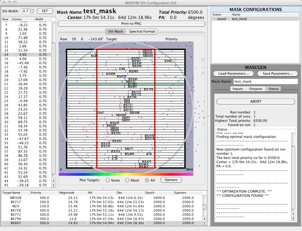
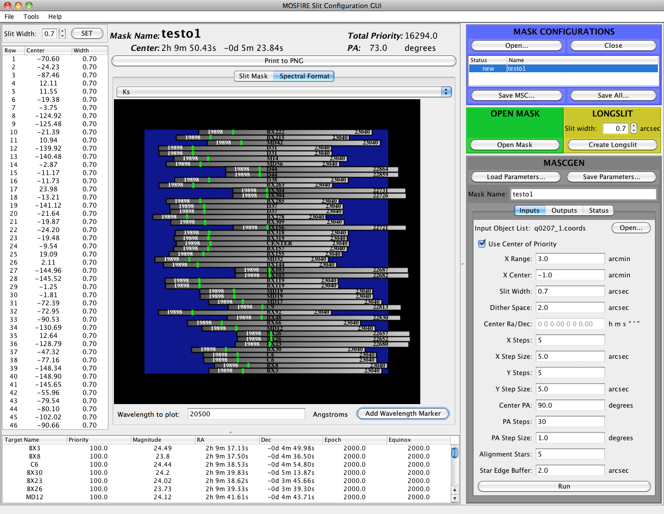
Instead of using milled aluminum slit masks requiring daily change-outs as for LRIS and DEIMOS, MOSFIRE features a cryogenic configurable slit unit (CSU) developed in collaboration with the Swiss Center for Electronics and Microtechnology (CSEM) that can position up to 46 slits, each of length 7.0″, to 10 µm (0.01″) precision anywhere within the MOSFIRE imaging field of view. Instead of submitting mask designs one month in advance of an observing run to allow time for their slitmasks to be milled, MOSFIRE observers can (in principle) use the instrument’s slit configuration GUI (see Fig. 2 below) to design mask layouts that can be altered in real time, or even designed minutes before their use. Users of LRIS and DEIMOS slitmasks will find the GUI to be easy to operate, requiring only a list of prioritized potential targets in the same format employed by the AUTOSLIT or DSIMULATOR programs for mask design on LRIS and DEIMOS. Mask configurations, as well as several other associated data products, are saved electronically; masks can be prepared at one’s home institution well in advance of an observing run or in near-real time for those observations for which advance planning is not possible. Similarly, users may take an existing mask design and change all of the slit widths in real time if observing conditions warrant.
|
|
MOSFIRE can also be used as a long-slit spectrograph. Slits up to 6.1′ long can be formed by aligning adjacent slits. The height of each individual slit is 7.0″, but when two pairs of bars are aligned to produce a longer slit, the overlap between bars is eliminated and the slit length becomes a contiguous 15″. Astronomers who do not require the multiplexing advantage offered by MOSFIRE will still find it to be an extremely effective single-target spectrometer. Users of NIRSPEC’s low-resolution mode (R ≈ 1300 with an 0.75″ slit) will find MOSFIRE to be effective for the same science, with significantly improved sensitivity due to much lower detector noise and significantly higher spectral resolution.
As with the ESI spectrograph on Keck II, MOSFIRE is equipped with an open-loop flexure compensation system capable of reducing image motion at the detector to < 0.1 px for both imaging and spectroscopic modes. Guiding is accomplished via a fixed (6.6′ off-axis) CCD camera with a field of view of 2.9′ × 2.9′, using the same MAGIQ guider system as implemented on other WMKO instruments. Slitmask alignments, as well as long-slit target acquisitions, will use the same Slitmask Alignment Tool GUI that has recently been commissioned on LRIS.
While final numbers await on-sky confirmation, based on the measured throughput of the optical components and the detector performance we can predict that limiting magnitudes in imaging and spectroscopic modes will be as shown in Table 1 below. In spectroscopic mode, dark current and detector noise will be negligible for typical integration times, so the sensitivity depends greatly on the true sky continuum between OH lines.
| Passband | Sensitivity S/N=10 in 1000 s |
|||
|---|---|---|---|---|
| Imaging Mode | Spectroscopic Mode | |||
| mag (Vega) |
mag (AB) |
mag (Vega) |
mag (AB) |
|
| Y | 24.4 | 25.0 | 20.9 | 21.5 |
| J | 23.7 | 24.6 | 20.4 | 21.3 |
| H | 22.5 | 23.9 | 20.1 | 21.5 |
| K | 21.7 | 23.6 | 18.6 | 20.5 |
The angular size of the sky area imaged onto the MOSFIRE detector is limited by the size of the detector (2040 px × 0.1798″ px-1 = 366.8″ square, projected onto the sky), by the CSU baffle close to the telescope focus, and by a circular baffle in front of the field lens just after the CSU, which has a measured angular diameter projected onto the sky of 414″ (6.9′) and corresponds closely to the unvignetted collimator field of view. Thus, the geometry of the MOSFIRE field is a 6.12′ square intersected with a 6.9′ diameter circle (see Fig. 3 below). The collimator field of view was designed to allow slits to be placed anywhere within a rectangular 3.0′ × 6.12′ region without vignetting.

|
MOSFIRE’s optics were designed to re-image the Keck Cassegrain f/13.66 focal plane (with a nominal plate scale of 0.72516 mm/″) onto the HAWAII-2RG™ detector (17.984 µm pitch at 77 K) with a plate scale of 0.18″ px-1; i.e., a focal reduction of 7.25 times. A polynomial mapping solution had rms of 0.05 px in going from CSU to detector, and 0.007 mm in mapping pixels to mm in the telescope focal plane. The closest linear mapping solution (i.e., including only a scale factor and rotation) has rms=0.18 px (or 0.03″), or distortion of only ~0.2%.
A custom-ruled diffraction grating was designed specifically for our application in orders 3, 4, 5, and 6 with a 40° included angle and angle of incidence (AOI) of 42.6° (H and K) and 41.5° (Y and J). The grating has 110.5 lines mm-1 with a blaze angle of 21.93° (first order blaze of 6.35 µm), and was replicated onto a Clearceram®-Z (OHARA) substrate, with a gold-coated ruled surface. As built, MOSFIRE achieves its design specification on resolutions as shown in Table 2. Because of the relatively steep angles of incidence for the MOSFIRE spectroscopic modes, there is significant compression in the spectral dimension of the dispersed images of slits as recorded on the detector. The (average) anamorphic factors are 1.357 for HK mode and 1.335 for YJ so that in spectroscopic mode, 1 pixel in the dispersion direction maps to 0.1798 × 1.335 = 0.240″ for YJ and 0.1798 × 1.357 = 0.244″ for HK. Thus, a slit corresponding to 0.6″ on the sky produces 0.6/0.240 (0.244) = 2.50 (2.46) pixel slit image at the detector. The nominal 0.7″ slit would correspond to FWHM=2.92 px for YJ spectroscopic mode and FWHM=2.87 px for HK spectroscopic mode in the spectral direction.
| Passband | Spectral Resolution R | |||
|---|---|---|---|---|
| 0.70″ slit width |
0.48″ slit width (2 px projected) |
|||
| Y | 3380 | 4960 | ||
| J | 3310 | 4930 | ||
| H | 3660 | 5340 | ||
| K | 3620 | 5280 | ||
In imaging mode, MOSFIRE’s optics deliver images < 0.18″ rms diameter over the entire field, so that even on the best nights the near-IR seeing will not be degraded by the MOSFIRE optics. Instrumental throughput in imaging mode is estimated to be 57%, 58%, 62%, and 56% for Y, J, H and K, respectively, including all optics and the detector. In spectroscopic mode the throughput averages >30% over the full bandwidth in each order with blaze peaks ranging from 36%–43% (see MOSFIRE Expected Throughput).
Eight filters are installed in MOSFIRE’s dual filter wheels, with Y, J, and H filters serving both as order sorters and photometric filters, while in K band there is a wide-K filter for spectroscopy and a Ks filter for imaging. Also included are intermediate-band filters J2, J3, H1 and H2 with approximately half the bandwidth of the broadband filters. Unlike other near-IR instruments at Keck, MOSFIRE’s wide field of view requires large (170 mm diameter) filters, so that it has not been possible to populate the filter wheels with narrow-band or special-purpose filters.
MOSFIRE’s optical design also includes an accessible pupil image and cold stop. The stop is implemented with an iris that can be opened to a circle that circumscribes the Keck primary mirror image or can be closed down to a hexagon that matches the primary mirror shape. In the latter mode the mechanism then tracks the pupil image, similar to NIRC2. All mechanisms have been tested extensively and successfully at their normal operating temperature.
Light-leakage and scattered light inside the instrument is very low. In 1800 s dark frames, the mean signal is < 0.008 e–s-1px-1. The HAWAII-2RG™ detector was successfully implemented using the SIDECAR ASIC (application specific integrated circuit) electronics. With a reverse bias of 300 mV and an amplifier gain giving 2.15 e– per DN, noise measurements achieve 4.9 e– rms with 16-pair Fowler sampling and a floor of 3 e– rms at 64 Fowler pairs. Up-the-ramp sampling is also implemented.
MOSFIRE’s software includes a full graphical interface for the observer (see Fig. 4 below), providing an easy means for configuring the instrument (in most cases via a single button click) and taking exposures. FITS files generated by MOSFIRE contain extensions with detailed information on everything in the instrument, including target names plus physical and sky positions of the masking bars (which is similar to DEIMOS). Scripts can be written to execute a series of actions, and considerable attention has been given to error-trapping.

|
The MOSFIRE slit configuration GUI (MSCGUI) will be available in a standalone version allowing any user to create masks (e.g.) on their own laptops or desktop computers. The MSCGUI running on the observers’ console can both create new masks and ingest previously designed masks, and then can send the configuration (once the user is satisfied) to set up the CSU. As shown in the bottom panel of Fig. 2, the MSCGUI has a mode showing the spectral coverage falling on the detector for all slits, in any of the four spectroscopic bands. Any target list with accurate relative astrometry (RA and Dec), regardless of the source, can be used as input to MSCGUI. Tools are available which use accurate mapping of the CSU plane onto the sky, and the CSU plane onto the detector, and both the telescope and the MOSFIRE focal planes will have essentially rectilinear mapping onto RA and Dec due to low distortion.
Many of the most exciting applications of astronomical spectroscopy are the most difficult, requiring extremely long integration times even on a 10 m telescope. By providing the ability to observe many objects at once in the near-IR, MOSFIRE will make such challenging observations feasible for the first time. We are eager to exploit this innovative new instrument to study topics ranging from substellar mass objects in young star clusters to high-redshift galaxies and the intergalactic medium. Observers will find a wide range of applications for MOSFIRE, helping keep Keck at the forefront of astronomy for years to come. ✶
Reference
- McLean, I. S., Steidel, C. C., Epps, H., Matthews, K., Adkins, S., Konidaris, N., Weber, B., Aliado, T., Brims, G., Canfield, J., Cromer, J., Fucik, J., Kulas, K., Mace, G., Magnone, K., Rodriguez, H., Wang, E., & Weiss, J. (2010). Design and development of MOSFIRE: the multi-object spectrometer for infrared exploration at the Keck Observatory. Proceedings of the SPIE 7735, 77351E-77351E-12.
OSIRIS Move Gives Keck I Dedicated AO Science Instrument
James E. Lyke, Support Astronomer, WMKO

|
The OSIRIS integral-field spectrograph was moved from Keck II to Keck I on January 17 and 18, 2012, in order to give Keck I an instrument which can take advantage of the adaptive optics (AO) and laser guide star (LGS) systems recently commissioned on that telescope. Immediately before the move, OSIRIS was serviced to repair a non-functioning lenslet mask slide. OSIRIS has now been aligned to the Keck I AO bench and on-sky engineering began March 1, 2012. Seven nights of engineering will be dedicated to integrating OSIRIS with the Keck I AO system, the Keck I LGS system, and returning OSIRIS to science operations. The first OSIRIS-LGS science night on Keck I is scheduled for May 29, 2012. ✶
“Target of Opportunity” Keck Images Prove Crucial in Characterizing the M101 Supernova Progenitor Star
Peter E. Nugent, Professor, Lawrence Berkeley National
Laboratory/UC Berkeley
Joshua S. Bloom, Professor, UC Berkeley/Lawrence Berkeley National
Laboratory
On August 24th of last year a supernova was discovered in the Pinwheel Galaxy (Messier 101) just hours after its explosion. At 21 million light-years away, SN 2011fe rose to magnitude 9.9, becoming the 5th brightest supernova seen in the last century and the closest Type Ia supernova discovered in the last 25 years. Immediately, our group conducted a search for potential progenitors in pre-explosion HST images. Given the distance to M101 and the depth obtained in the Hubble Space Telescope’s Advanced Camera for Surveys (ACS) F814W images, we knew that the constraints from these observations would be almost 2 orders of magnitude more sensitive than those for any other Type Ia supernova seen to date.

|
The first problem facing us was how best to astrometrically align the HST images with ones on which we could see the supernova. The images used to find SN 2011fe were taken on the Palomar Oschin Schmidt. However, given pixels 1″ on a side and seeing near 2″, they were less than ideal for identifying potential progenitor systems. Thus we asked for “target of opportunity” (ToO) observations of the field of SN 2011fe with the Near-Infrared Camera 2 (NIRC2) mounted behind the adaptive optics (AO) system on the Keck II telescope. University of Hawaii observers Alan Stockton and Hsin-Yi Shih were kind enough to oblige us. But then we faced our second problem: at this point in the year, M101 was setting quickly in the west, and the telescope limits on Keck II provided us with a window of opportunity of only 11 minutes after astronomical twilight ended to complete the observations. Fortunately for us, SN 2011fe had brightened by nearly 3 magnitudes since discovery and was now brighter than 14th magnitude; thus, we were able to use the supernova itself as the necessary guide star for the adaptive optics tip-tilt correction. On August 26th, we obtained a series of H-band images starting in twilight (see Fig. 6 above).

|
These images allowed us to achieve a 1σ error circle of 21 mas for the position of the supernova on the pre-explosion HST images (see Fig. 7 above). Using this, we were able to rule out any companion stars brighter than an absolute magnitude of approximately 0.5 — roughly an upper limit of 2–3 solar masses on the zero-age main-sequence. These direct observations of the progenitor system of SN 2011fe exclude several potential symbiotic progenitors like RS Oph and probably T CrB as well as all red giant companions. This work can be seen in the Nature article, “Exclusion of a luminous red giant as a companion star to the progenitor of supernova SN 2011fe” by Li et al. (2011). ✶
Recent NIRC2 Enhancements: Filters, Throughput Monitoring, and KOA
Hien D. Tran, Support Astronomer, WMKO
Bob Goodrich, Observing Support Manager, WMKO
Tatyana Panteleeva, Interferometer Operator, WMKO
NIRC2 gets new filters
NIRC2 was successfully serviced in September 2011. The main goal of the service mission was to install a number of filters. This was the first time NIRC2 had been opened since 2003 when it was last serviced, also to install filters. Led by NIRC2 Principal Investigator Keith Matthews, we installed seven new filters: z, Pa γ, He IA (10,830 Å), Br α and Br β continuum, L-wide, and a Y filter, the latter procured with generous support from Mike Liu (UH-Manoa). To make room for the new filters, the L-undersize and a duplicate Br α filter were removed. Detailed characteristics of the newly installed filters are available on the updated filters page. In addition to the filter installation we also inspected the general state of the instrument, fixed the temperature read-back problem for the single-stage cold head, and purged both cold heads. These are the original cold heads that have been running on NIRC2 for over 10 years since commissioning in 2001, and they may be showing some signs of old age, as they need to be run at slightly higher (+2 RPM) speeds than in the past to keep NIRC2 at nominal operating temperatures.
The new filters extend the wavelength coverage of NIRC2 down to 1 µm, improving the multi-color photometry capabilities, and the L-wide filter is expected to improve efficiency for both imaging and spectroscopy at that wavelength. A z-band image (see Fig. 8) obtained with the narrow camera during a post-service engineering night in September 2011 shows that we achieve a FWHM ≈ 30 mas and Strehl ratio of ~ 13% on an R ≈ 10 mag natural guide star. Observers are encouraged to check out the new filters and consider them for their future use of NIRC2.

|
Throughput monitoring
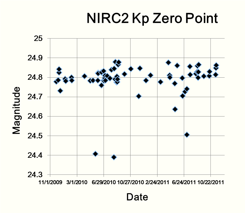
As part of the laser guider star adaptive optics system checkout at the beginning of nights whenever NIRC2 is on sky, seeing measurements are obtained by imaging an R ≈ 10 mag star using the narrow camera in the Kp filter, with the deformable mirror (DM) loop open. We have used these data collected over the years to monitor the throughput of NIRC2. The data were initially dark-current-subtracted and flat-fielded. Then a background determined by the median of the modes of three surrounding empty fields was subtracted. Aperture photometry was performed by measuring the total flux within an aperture of 100-pixel (1″) radius. Then the zero-point was calculated from the standard formula
m = -2.5 log (DN/s) + zero-pointwhere DN/s is the measured counts divided by the total exposure time, and m is the known stellar magnitude in K. The results are plotted in Fig. 9.
|
Measurements from nights that were indicated as cloudy by either the Keck nightlog summaries or the CFHT SkyProbe measurements were excluded. Figure 9 shows several low points from nights that had exceptionally poor seeing although they otherwise appeared clear. Poor seeing can certainly decrease the number of counts included in the 1″ radius software aperture of the procedure. Ignoring those questionable data points gives a Kp zero-point of 24.81 ± 0.04. These data have not shown any measurable degradation in the throughput of NIRC2 over the past couple of years.
NIRC2 data coming soon to KOA
The Keck Observatory Archive (KOA) has been serving data from HIRES since August 2004 and NIRSPEC since May 2010. Soon users can look forward to the availability of nearly half a million NIRC2 raw FITS files obtained since 2001 in the archive. The NIRC2 data release is scheduled for April 2012. Principal Investigators normally have proprietary access to their data for at least 18 months after the date of observation. For data access and more information, go to the KOA User Interface. Archival use of Keck data has contributed to several recent refereed papers, and observers are encouraged to tap into KOA when they consider their next scientific investigation. ✶
New HIRES Slit Guider Sees More Sky and Fainter Targets
Bob Goodrich, Observing Support Manager, WMKO
Sean Adkins, Instrument Program Manager, WMKO
Scott Dahm, Support Astronomer, WMKO
In February 2012, we installed a new slit guider camera for HIRES. The ancient Photometrics CCD and its controller were replaced by a MAGIQ camera, providing improved performance and reliability. We are also working on a concept for a second offset guiding channel that will have a larger field of view, patrolling an annular ring of sky around the HIRES science field. Our goal is to complete this second system by the end of September.
The new slit-viewing camera is a relatively straightforward detector change. The same filter wheel and guide camera focal reducing lens were used. The new CCD provides a finer plate scale and allows a somewhat larger field of view, but in HIRES the usable slit guider field of view is limited by the decker and the size of the image rotator, so there is only a modest improvement in sky coverage. However, the new detector has higher quantum efficiency and lower read noise, which will help when guiding on “faint fuzzies.”

|
The new system was installed on February 15–16, and the guider image quality appears to be good. Commissioning was performed on the first half of March 1, 2012, and HIRES observers are enjoying the benefits of the new system. ✶
DEIMOS Works Through Some Glitches But Remains Fully Functional
Luca Rizzi, Support Astronomer, WMKO
Gregory D. Wirth, Support Astronomer, WMKO
A series of problems affecting the flexure compensation system (FCS) of DEIMOS has unfortunately surfaced in the past few months. The initial symptoms appeared around July of 2011. To compensate for flexure during its rotation, DEIMOS uses a tent mirror to account for displacements of the beam in the spectral direction, and physically translates the CCD dewar to correct flexure in the spatial direction. For two consecutive nights in July, the dewar translation stage reached its hardware limits, thus cutting power to the stage and requiring manual intervention to restore the full functionality. The problem was eventually traced to an overly-generous permitted range of motion for the stage; once the stage was moved to its software limit, gravity-induced motion could force the stage into the “hard limit.” The problem was fixed by defining more restrictive software limits.
During the tests required to fix this problem, DEIMOS was rotated frequently, and several FCS images were taken at different rotation angles. This led to the discovery of two additional problems. First, it was discovered that at certain rotation angles the images produced by the FCS CCDs were heavily affected by electronic noise, to the point of being essentially useless. This problem turned out to be quite puzzling, because none of the obvious components of the video signal chain was found to be faulty. Eventually, our summit instrument engineer Dwight Chan traced the problem to a loose connection on the high voltage cable that provides power to the CCD dewar ion pump, which passes very close to the FCS CCD electronics. At certain instrument rotator angles the connection was unstable, thus generating the electrical interference observed in the FCS CCDs images. Secondly, we discovered a problem with the light coming from the copper arc lamps which generate the FCS spectrum. In DEIMOS, optical fibers are used to relay the light from those lamps all the way to the telescope focal plane, but we discovered that at certain DEIMOS rotation angles the light did not reach the CCD. The problem was easily traced to a loose cable right next to the exit point of the optical fibers, and vignetting the aperture. The problem was resolved when we secured the cable.
Finally, a third (and still unresolved) problem was discovered during this sequence of tests. Under certain conditions, the flexure observed in DEIMOS exceeds the “capture range” of the FCS, and thus full flexure correction is impossible. Further analysis has revealed that the flexure properties of the grating slider assembly have changed significantly from the commissioning phase to now. We have also observed that the flexure properties are different for the three sliders, and that they also strongly depend on the clamping angle, which is the rotation angle at which the grating is selected and clamped.
At the time of writing, we haven’t yet been able to identify the reason for this behavior. The clamping system, the slider assembly, and the grating cells have been carefully inspected; shims have been added in different places to modify the behavior of the clamps; adjustments have been made to the components of the system, but unfortunately none of these interventions has managed to eliminate the problem. However, we have identified several potential culprits for further investigation and are committed to fixing this problem.
As a temporary solution, we have deployed a script that observers can use to automatically rotate DEIMOS to the optimal rotation angle for clamping up their desired grating. These optimal positions were derived from analyzing the grating flexure curves, and their use ensures that the clamping always happen near the center of the flexure curve.
UCO/Lick staff have been extremely helpful in troubleshooting this problem, and a visit by them is currently being arranged to inspect the slider assembly and hopefully correct any defects. ✶
Recent Software Upgrades: Making Your Life Easier, Bit by Bit
Luca Rizzi, Support Astronomer, WMKO
The WMKO staff constantly strives to help you maximize your efficiency by coming up with new tools to make the observing process easier for you. Sometimes our inspirations come from watching you operate the instrument, whereas other times you give us ideas for possible improvements on your Post-Observing Comment forms. Below, we highlight some of the recent innovations you may be interested in knowing about. If you think of others, please let us know.

NIRSPEC: New format simulator
There is now a feature in the NIRSPEC Echelle Format Simulator (EFS) GUI (right) that allows the user to lock-in a desired instrument setup (e.g., grating angle, filter, and slit). This is intended to avoid accidently changing a configuration once an observation sequence has begun. Another improvement to the EFS is an automated variable-intensity flat field bulb control, which shortens the time needed to obtain internal flats of sufficient signal-to-noise, especially at shorter wavelengths, thereby increasing efficiency on sky. Furthermore, the user can now specify a desired count level for their flats, and the software sets the appropriate integration time and number of co-adds to safeguard the detector from over-exposing to avoid charge persistence.

ESI/LRIS/DEIMOS: Dual star alignment tool
Ever wondered what the best way is to put two objects on the same slit? Using the proper tool, of course! The new LongSlitAlign tool (left) is now available for ESI and will soon be available for LRIS and DEIMOS. It requires the observer to provide the coordinates of two locations measured on an image of the slit (acquired with the guider or the science camera), and the coordinates of the two targets; it then applies the necessary instrument rotation and telescope translation commands to center the targets on the slit.New instructions on rsync
The rsync command provides a convenient way to transfer your data onto your laptop or back to your home institution. By transferring only those files which have changed since the last copy was made, rsync operates with high efficiency. Our new web page provides detailed instructions on how to use rsync from Keck.
LRIS/DEIMOS: GUI to observe flux standards
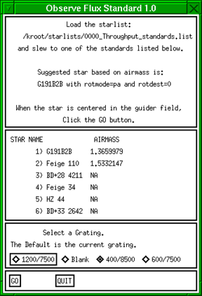
The handy Observe Flux Standard GUI (right) allows the observer to take slitless spectra of one of the selected flux standards we use for our throughput monitoring program. After you select the grating, the software automatically chooses two or three different wavelength settings that optimally cover the available spectral range. You access the tool through the background menu. A pipeline currently under development will reduce the data and provide the observer with a throughput estimate.LRIS: Automatic starlist generation.
We’ve noticed that a common problem when aligning slitmasks is that the observer enters incorrect coordinates into the starlist file. Observers using LRIS can avoid this pitfall by automatically generating starlists based on which slitmasks are loaded in the instrument. The new Generate Mask Starlist tool can be selected from the pull-down background menu under LRIS Utilities. It reads the slitmask database to determine the proper RA, Dec, equinox, and position angle for each mask, and creates a file which you then copy into your starlist directory.Starlist submission webtool
Submitting a starlist has never been easier! From your observer login page, choose “Manage your target lists here.” Select a directory from the left window, and upload your file using the right window. The starlist will end up in the selected directory waiting for you to show up at the telescope. This option is particularly handy for observers at our mainland observing sites.

Target visibility webtool
A recent planet-hunting HIRES observer pointed out that we needed a better tool to help observers visualize which targets are currently accessible and how long they would remain observable before hitting a telescope limit. WMKO Software Engineer Shui Kwok responded by building a web-based tool which shows the current view of the sky in a Mercator projection. In this plot (left), the red line indicates the horizon, the grey line represents the telescope limits, and color-coded symbols indicate which targets are currently observable (green) and which are not (grey). The plot also displays the current telescope position so that the observer can easily see which targets will require the shortest slew. The advantage of this view is that the observer can easily determine the amount of time until any given target reaches a telescope limit by reading the number of hours between the current position and the corresponding telescope limit at that declination. You can generate a visibility plot for a given target by using the new web-based starlist tool mentioned above to open your starlist, then clicking the Show Visibility button. ✶Using Keck Spectra to Probe a Mysterious Star System in Taurus-Auriga
Scott Dahm, Support Astronomer, WMKO
If you’ve watched the liquid in a hot pot of water circulate just before it boils, then you’ve witnessed the process of “convection” in action. But convection isn’t something that only happens on your stove — it also happens inside of stars.
Most stars only experience convection in their outermost layers, preventing the elements in the core of the star from mixing with the material in the outer layers. But the youngest and lowest-mass stars are “fully convective,” meaning that the convection process extends all the way down into the core (middle) of the star and thus mixing all of the contents of the star together. When the core temperatures of such stars reach 2.5 to 3.0 million degrees Kelvin, they begin fusing lithium with hydrogen nuclei to form helium. Convection circulates material through the core of the star, causing the fusion process to consume all of the available lithium on a relatively short timescale of several tens of millions of years. Given how quickly the lithium is consumed, if we observe a low-mass star and can detect the characteristic absorption features from neutral lithium at 6708 Å, we know that the star must be quite young.
The object HBC 425 (also known as St 34) was once thought to be a single star but is now recognized (thanks to spectroscopy) as a pair of stars having the same temperature and luminosity. Given its proximity to the Taurus molecular clouds and its strong T Tauri-like attributes, HBC 425 was assumed to be a young pre-main sequence star; however, White & Hillenbrand (2005) discovered that both components of the spectroscopic binary show substantial differences between the ages suggested by their observed lithium depletion (25,000,000 yr) and the much younger ages suggested by their presumed temperature and luminosity (8,000,000 yr). How can we resolve this discrepancy?

|
In a recently-accepted paper, my fellow WMKO Support Astronomer Jim Lyke and I used the NIRSPEC instrument on the Keck II telescope to observe HBC 425C, a third component of the HBC 425 system lying 1.23″ away from the primary pair. Thanks to incredibly sharp images provided by the Keck II adaptive optics system, Jim and I obtained high-spatial-resolution, low-spectral-resolution, near-infrared spectra which revealed HBC 425C to have an M5.5 spectral type. I also obtained a complementary high-resolution optical spectrum of HBC 425C with the HIRES instrument on Keck I in excellent seeing conditions that provided good spatial resolution. From these spectra, we detected strong lithium absorption lines in these spectra of the third star in the system (see Fig. 11 above). Although the presence of lithium in the photosphere of HBC 425C does not immediately resolve the discrepancy between the two independent age estimates for HBC 425, if further studies determine that lithium is even minimally depleted relative to interstellar abundance levels, this will strongly suggest that the star system is both older and closer to us than previously suspected, thus resolving the mystery. ✶
Back Issues
Please see the Keck Observers’ Newsletter Archive.