The table below shows the filters are currently available with NIRC2. Note that several new filters that were installed in September, 2011 are now included. Filter transmission curves are included as they become available.
(Clicking on a filter name of several filters will bring up a plot of that filter's transmission curve.)
|
Filter |
Central wavelength (µm) |
Bandpass |
Cut-On Wavelength (µm) |
Cut-Off Wavelength (µm) |
Photometric |
Sky (mag./ sq. arcsec) |
T(max) (sec) |
1.0311 |
0.0481 |
1.007 |
1.0551 |
||||
1.0180 |
0.0996 |
0.9682 |
1.0678 |
||||
|
1.248 |
0.163 |
1.166 |
1.330 |
|
|
|
|
|
1.633 |
0.296 |
1.485 |
1.781 |
|
|
|
|
|
2.196 |
0.336 |
2.028 |
2.364 |
|
|
|
|
|
2.146 |
0.311 |
1.991 |
2.302 |
24.53 |
12.2 |
630 |
|
|
2.124 |
0.351 |
1.948 |
2.299 |
24.74 |
12.2 |
630 |
|
3.5197 |
1.3216 |
2.8589 |
4.1805 |
||||
|
3.776 |
0.700 |
3.426 |
4.126 |
|
|
|
|
|
4.670 |
0.241 |
4.549 |
4.790 |
|
|
|
|
Narrow Band |
|||||||
1.0847 |
0.0182 |
1.0756 |
1.0938 |
||||
1.096 |
0.016 |
1.088 |
1.104 |
||||
1.2132 |
0.0198 |
1.2033 |
1.2231 |
||||
1.2903 |
0.0193 |
1.2807 |
1.3000 |
||||
|
1.5804 |
0.0232 |
1.5688 |
1.5920 |
|
|
|
|
1.5923 |
0.1257 |
1.5295 |
1.6552 |
||||
|
1.6455 |
0.0256 |
1.6327 |
1.6583 |
|
|
|
|
1.6809 |
0.1368 |
1.6125 |
1.7493 |
||||
2.0563 |
0.0326 |
2.0400 |
2.0726 |
||||
|
2.1686 |
0.0326 |
2.1523 |
2.1849 |
|
|
|
|
|
2.1281 |
0.0342 |
2.1112 |
2.1452 |
|
|
|
|
2.2622 |
0.0388 |
2.2428 |
2.2816 |
||||
|
2.2706 |
0.0296 |
2.2558 |
2.2854 |
|
|
|
|
2.2891 |
0.0267 |
2.2757 |
2.3024 |
||||
3.0629 |
0.1549 |
2.9855 |
3.1404 |
||||
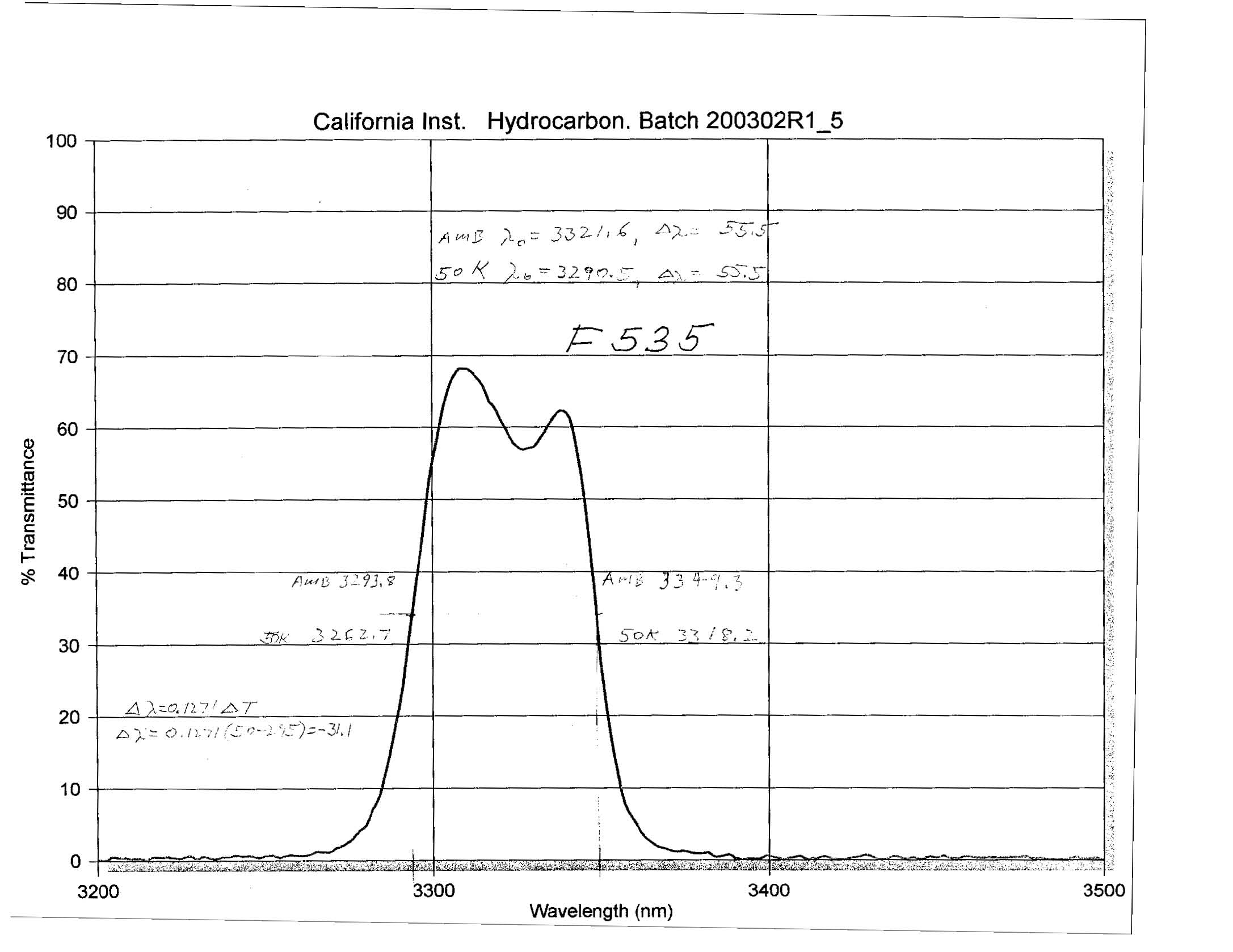
3.2904 |
0.0555 |
3.2627 |
3.3182 |
||||
3.987 |
0.069 |
3.952 |
4.021 |
||||
4.052 |
0.068 |
4.018 |
4.086 |
||||
counts/sec/pixel = (arcsec/pixel)^2 * 10^[0.4*(Z-S)]
where (arcsec/pixel) is the pixel scale, e.g. 0.040 for the wide camera.