Here we list three GUIs with which MOSFIRE observers will interact regularly.
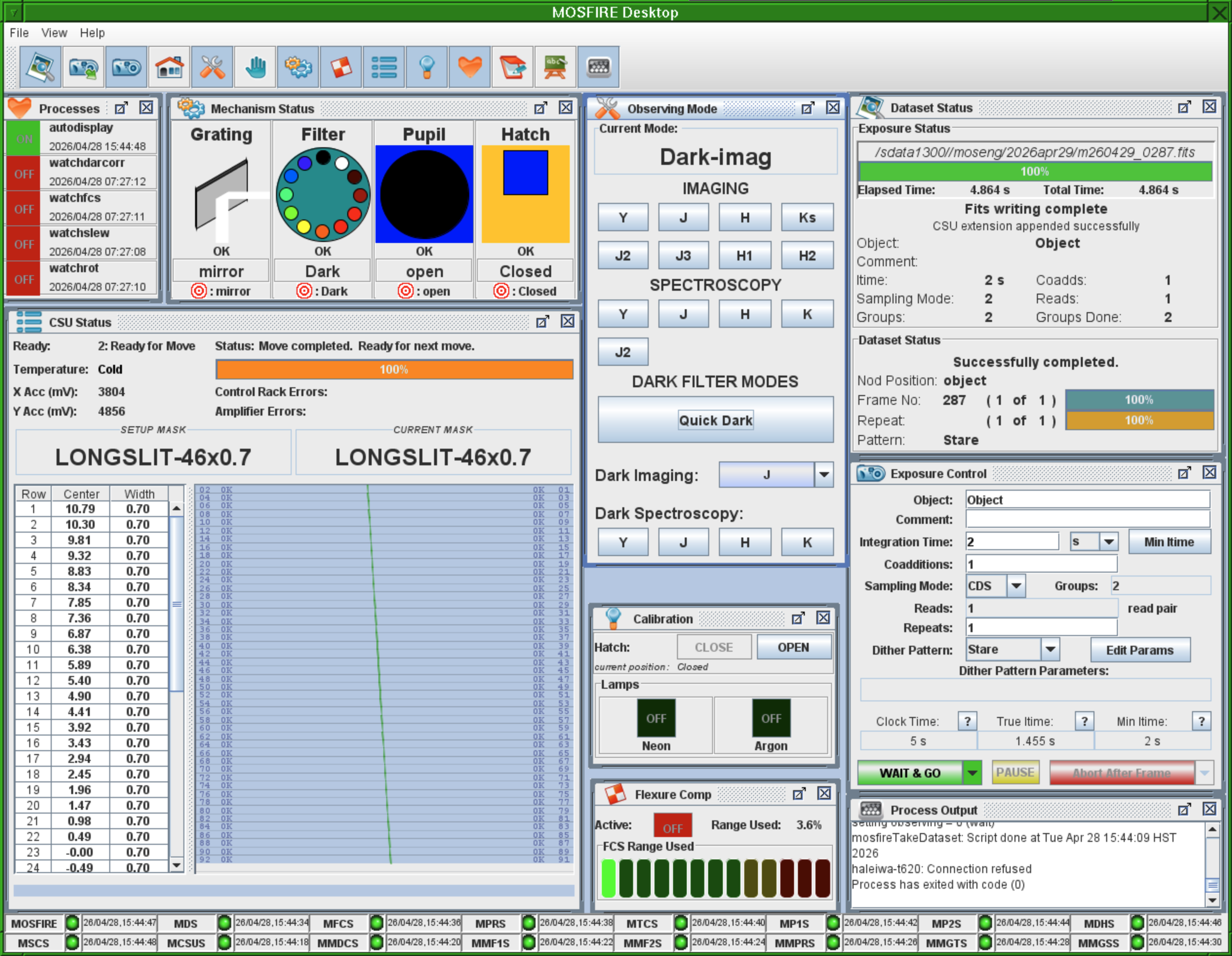
The MOSFIRE Desktop is your primary control for the MOSFIRE instrument. The only component of MOSFIRE not controlled by the MOSFIRE Desktop is the Configurable Slitmask Unit (CSU). The Desktop has many components which might initially seem intimidating, but a brief introduction to each should allay anxieties. Please find each component discussed on the image above starting from the upper left hand corner.
| Sub-GUI Description | Image |
|---|---|
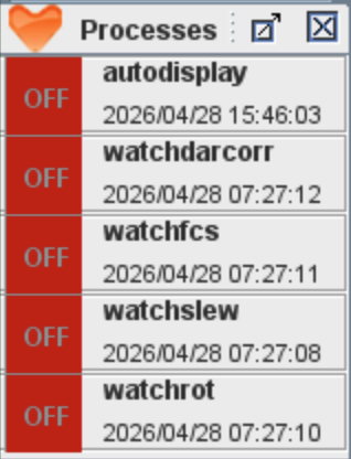
Heartbeat Process Monitor: Upper left hand corner. This is a visual of several processes which are monitored periodically. When functioning properly, each indicator is green. Momentary changes to red are not a cause for concern, but if any of the indicators turn red and remain red, or never turn green when the instrument is selected, notify your SA and OA. The processes indicated are:
|
|
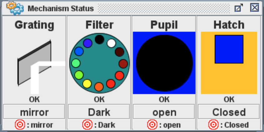
Mechanism Status - Middle left upper panel of the Desktop GUI. This panel indications the current status and target of each mechanism on the MOSFIRE instrument. These statuses will indicate the current observing mode. Status can have values of OK, Moving, Lost, Error. If statuses temporarily change to Error while the mechanisms are not being sent for a move, then it is okay to disregard. If the status stays in Error mode, becomes Error during a mechanism move, or moves to Lost, please contact your SA. If any mechanism move does not complete, appears "stuck", or moves to the wrong mode, send the move again on the Observing Mode panel. If a second try fails, contact your SA
|
|
|
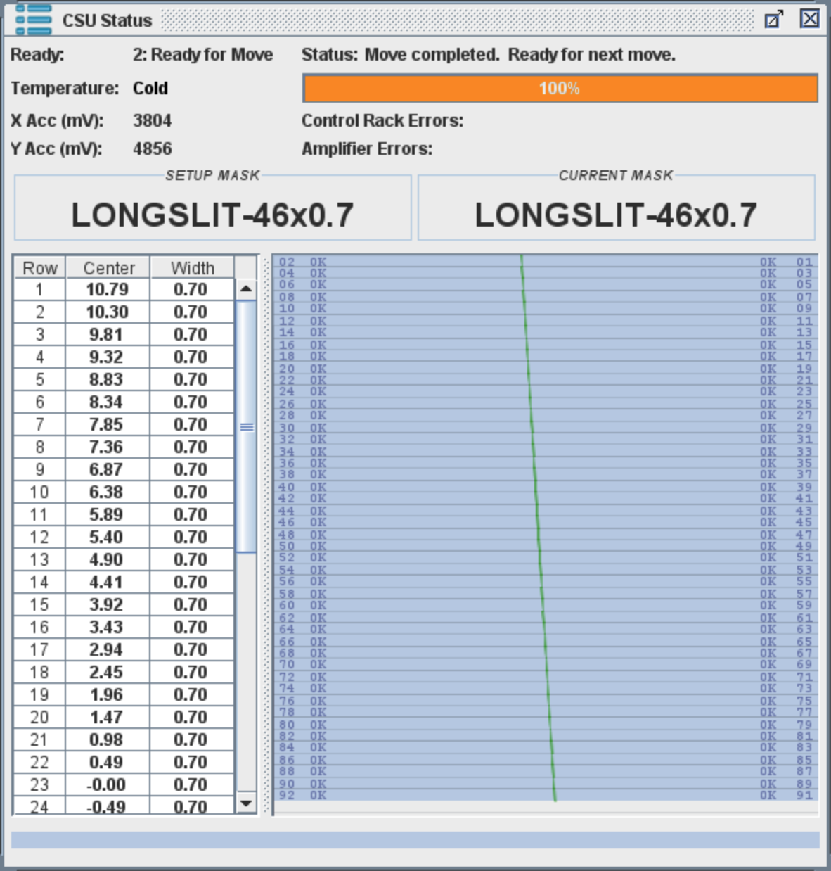
CSU Status - Lower left panel. Indicates the current status of the CSU (Ready for move, Errors, Moving, Powered off). Also indicates operating temperature, readings on the accelerometers, the name of the currently loaded mask and the mask to be set up, and the positions of each slit both visually and in a table of row number, center of the slit (relative to center of the CSU), and width of the slit (in arcseconds). Also includes a progress bar for CSU reconfigurations. Will indicate at the Status if a CSU Fatal Error has occurred. |
|
|
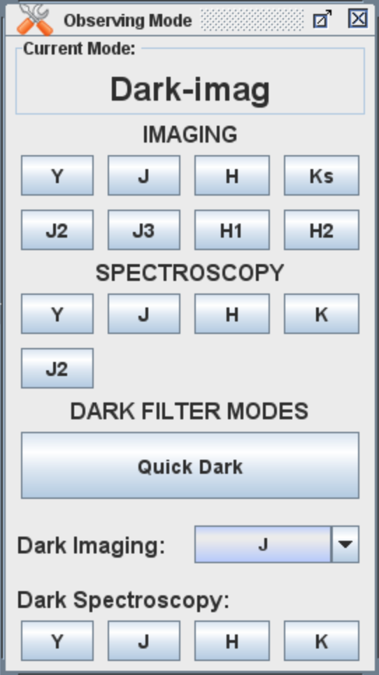
Observing Mode: Center top panel. This panel includes buttons to send a mechanism move to a list of pre-determined observing modes. Includes Imaging modes (moves to imaging filters and the mirror grating), Spectroscopy modes (moves to spectroscopy filters and the correct grating), and Dark modes. There is a known issue that moving from the narrow band filter NB1061 to “Quick Dark” on the Observing Mode panel does not result in a move. Please move to a specific Dark Imaging or Dark Spectroscopy mode instead. |
|
|
Calibration: Centermost panel. Includes Hatch moves to close or open the Hatch/Dust Cover, and buttons to turn off and on the calibration lamps. The MAGMA spectroscopy-mode calibration tool should make use of the lamp buttons unnecessary, but they will indicate if one of the lamps is on during the calibration script. Additionally, for J2 calibrations, arcs will need to manually be taken if desired, so these buttons can be used for that configuration. |

|
|
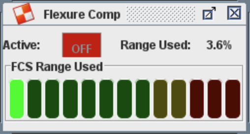
Flexure Comp: Center bottom panel. Indicates if the Flexure Compensation System is working, and at what percentage of its total capacity of compensation is being used. Includes a bar indicator, where the red range is associated with the possibility of oscillations resulting in doubled images (check output exposures for doubled images, this issue has not been reliably reproducible). |
|
|
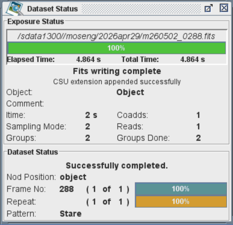
Dataset Status: Top rightmost panel. Includes a progress bar for your exposures, as well as the latest exposure name and location the exposure is being written to. Also includes a status for the data server and your exposure, the exposure parameters being used for the current or last exposure, and the status of the current or last dither pattern. |
|
|
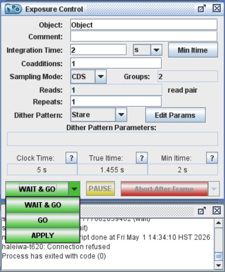
Exposure Control: Center right panel. This is where you will input your exposure parameters for the data-taking system. Includes such values as the Object name, comments, integration time, coadditions, sampling mode, read pairs, repeats, and dither pattern. You can start, pause, or abort an exposure sequence here. When the Dither patterns are changed from Stare, the currently loaded parameters will appear below in the Dither Pattern Parameters location. The observer can modify the size of a dither throw by pressing on the Edit Params button. The minimum integration time will change depending on the chosen sampling mode and read pairs, and will appear red if the integration time is below this minimum value. When these parameters are changed, click away from the most recently changed parameter to see the total clock time of the sequence. Three buttons are located at the bottom of the panel. One of these buttons is green to begin the exposure sequence, with three options given at the dropdown menu. Selecting one of the options will immediately execute this option. "Wait & Go" will wait to begin the exposure once all mechanisms are at the selected Observing Mode. "Go" will immediately begin the exposure sequence regardless of the Mechanism Statuses. "Apply" will not begin an exposure and will load the current exposure control parameters into the datataking system without beginning an exposure. This will be useful for long2pos sequences. The middle yellow button is "Pause", which will pause a current exposure, and can be resumed at the same button when desired. The red button lists abort options, which will allow the user to abort once the current frame is finished, immediately, abort after read, abort after coadd, and abort after repeat. |
|
|
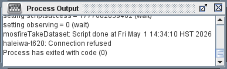
Process Output: Bottom right panel. This is a troubleshooting panel for your SA. Will indicate output messages about the scripts you are running on the desktop. |
|
|
MOSFIRE Server Statuses: Bottom bar of the MOSFIRE Desktop. This is a troubleshooting panel for your SA. Each dot is associated with a MOSFIRE server and its status as well as its response heartbeat. If a service is turned off the indicator will turn red. If a service stays red, contact your SA for assistance. |

|
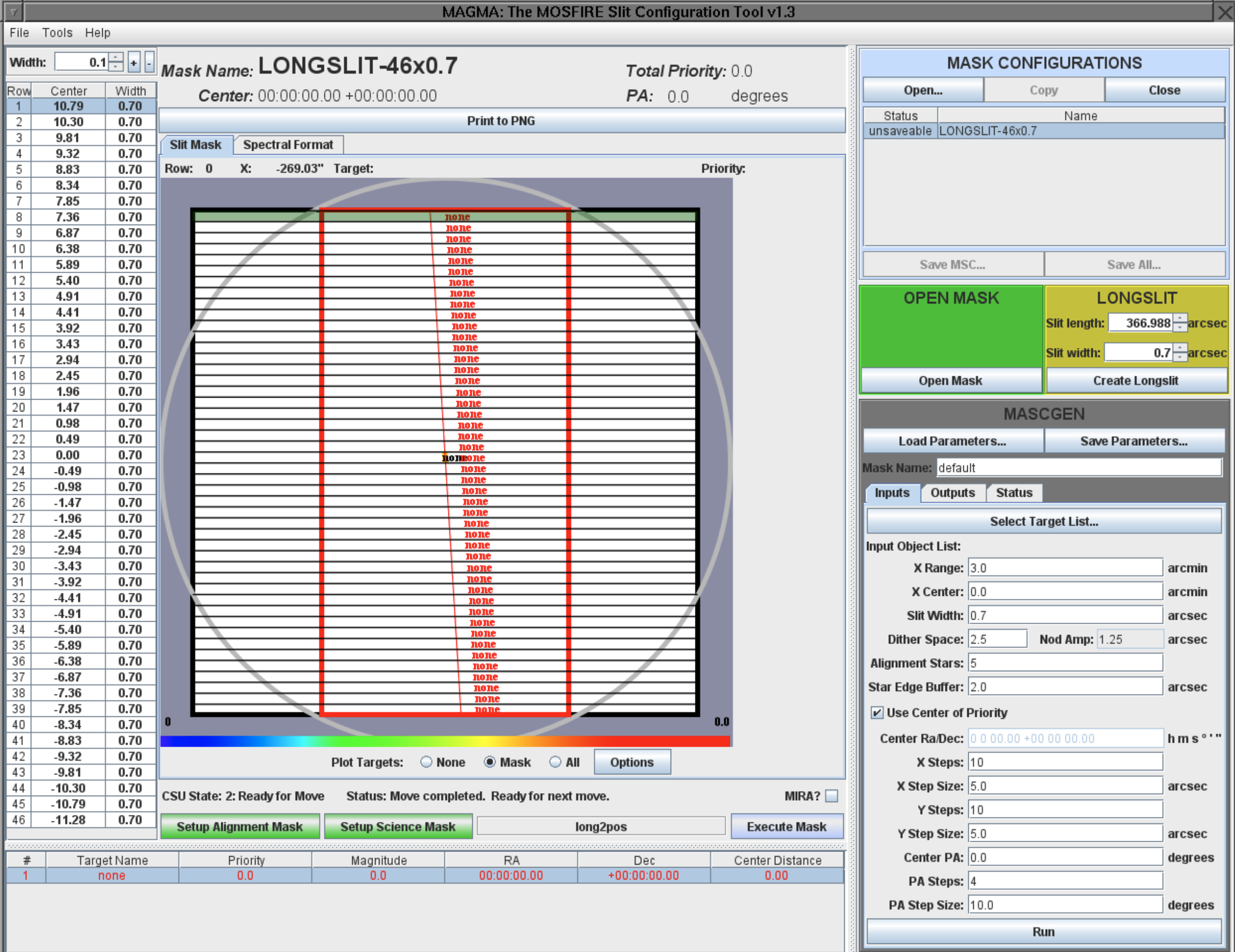
This GUI allows the user to control the Configurable Slitmask Unit, or CSU. It can also be used to design slitmasks on the MASCGEN panel and in the downloadable version (details here).
One can load premade mask designs uploaded to the Keck computer on the MASK CONFIGURATIONS panel. To remove a configuration from the list of loaded configurations, select the mask to remove and press the Close button.
OPEN mask designs and Longslits can be created quickly inside of the MAGMA GUI using the green and yellow panels under the mask configuration panel. Open masks are used for imaging and move all the bars to the edge of the CSU to reveal the whole field of view. Longslits can be created by specifying the width of the longslit and the length (note that each bar is 7” long, and a longslit that is the length of the entire CSU will be 366.988” long on the GUI). These premade designs will be loaded into the mask configurations panel after creation.
To execute a mask - forming the CSU into the design configuration - select the chosen design from the Mask Configurations panel, and click one of the green buttons at the bottom left corner of the GUI. “Setup Alignment Mask” will include alignment boxes from your mask design. “Setup Science Mask” will not include the alignment boxes. If you check the box that says “MIRA?” to the right of this panel, it will include a 35”x35” box used for the telescope focus procedure, MIRA, and is recommended for your first mask of the night.
The Setup buttons will not execute the mask. They will send the required move to each bar that will be needed to create your mask. When the setup is complete, the Execute Mask button will become green and this will execute the mask. We have enabled several pop up messages to verify that the correct configuration was selected, and that a CSU move is not being made that will likely result in a CSU fatal error. You can select on these messages not to display them at any time.
A CSU reconfiguration can take up to 6.5 minutes for a full reconfiguration. Partial reconfigurations, such as moving from a MIRA mask to an alignment mask, or an alignment mask to a science mask, take significantly less time, ranging from 30 seconds to 2 minutes. The Calibration Tool (used for spectroscopic calibrations) can be accessed at the top toolbar of the MAGMA GUI. This is located under the Tools tab, and is accessed by clicking “Calibration Tool…”. Default values are pre-loaded into the calibration tool. The calibration tool will automatically perform all necessary mechanism moves to take your calibrations such as moving gratings, filter wheels, and the hatch (if hatch moves are enabled), and turning off and on dome flat lamps and arc lamps.
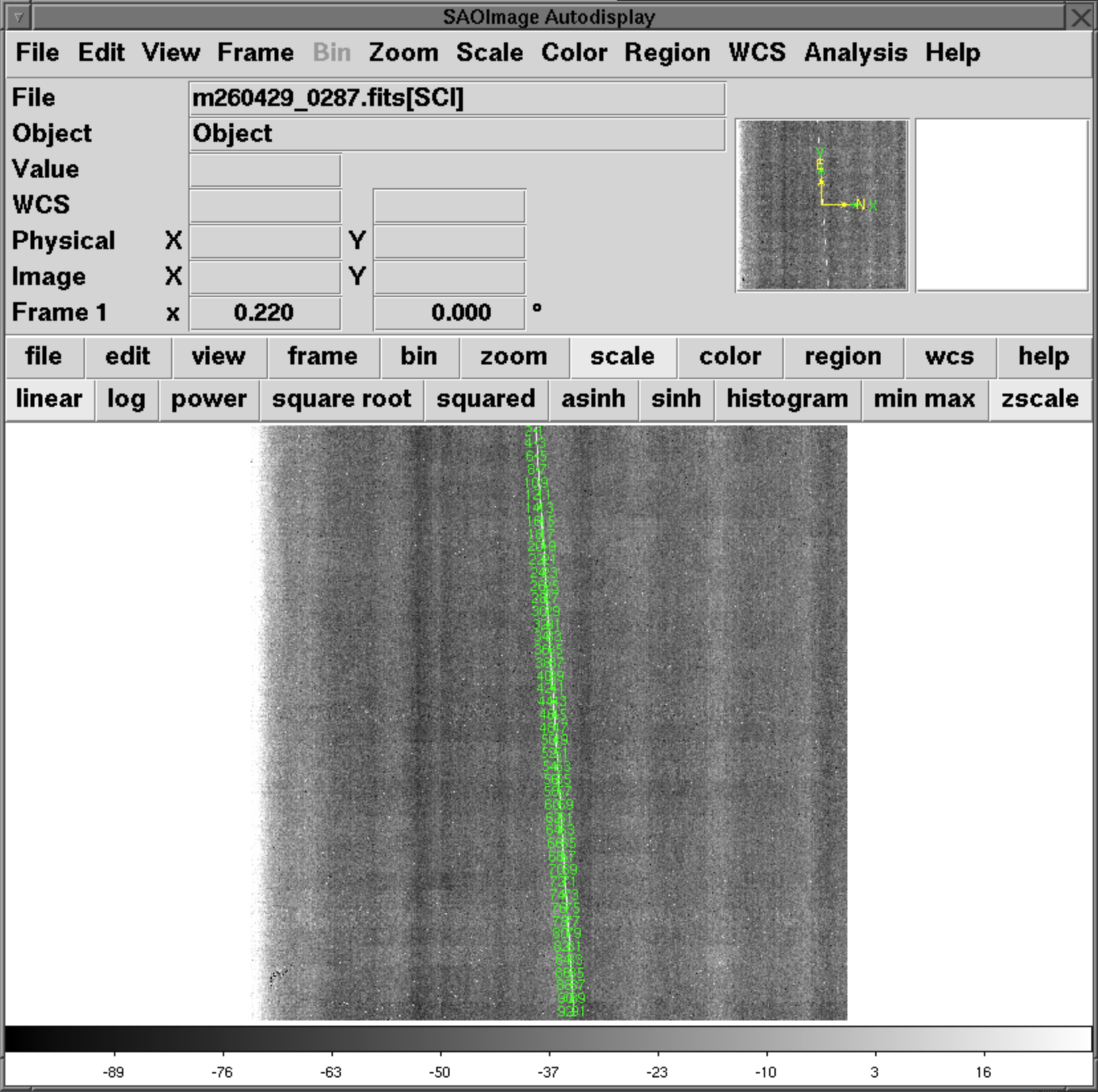
The autodisplay is a modified ds9 window which automatically displays the latest image taken with MOSFIRE. Press the ‘Tab’ button on your keyboard to display a difference image between the latest exposure and the previous exposure (excellent quick look for dithered images). If you are in imaging mode, press ‘Tab’ again to see the current imaging mosaic from your dither pattern. If you are in an imaging mode, 92 regions will be displayed indicating the positions of each CSU bar (as seen in the above internal image of a longslit). If the location of one of the regions significantly differs from where the bar is visually located, please contact your SA to re–initialize the bar.
When the Autodisplay is loaded, the region type that is automatically selected is the Projection region, so that the observer can quickly display counts. A known issue when creating these regions is that when a region is being created, if a new image finishes reading out and loads before this region is completed, the Autodisplay shuts down. To re-open the autodisplay, right click on the background, MOSFIRE Control Menu -> Subcomponents -> Restart DS9 Image Display.