
4.0 SYSTEM MODEL
TABLE 4-1. UISC Data Flow Drawing Tree
| 1.1 UI | 1.1.1 Setup & Acquisition | ||
| 1.1.2 Operator UI | |||
| 1.1.2.1 Loop Control | |||
| 1.1.2.1.1 Main Loop Control | |||
| 1.1.2.1.2 Auxiliary Loop Control | |||
| 1.1.2.1.3 Alignment Verification | |||
| 1.1.2.2 Exception | |||
| 1.1.2.3 Characterize & Optimize | |||
| 1.1.3 Engineering UI | |||
| 1.1.3.1 System Status | |||
| 1.1.3.2 Subsystem Engineering | |||
| 1.1.3.3 Alignment & Calibration | |||
| 1.1.3.4 Simulator Control | |||
| 1.2 SC | 1.2.1 Off-loading Control Loops | ||
| 1.2.1.1 Tilt Off-loading | |||
| 1.2.1.2 Segment Tilt Off-loading | |||
| 1.2.1.3 Coma Off-loading | |||
| 1.2.1.4 Focus Sensor Off-loading | |||
| 1.2.1.5 WFS Focus Off-loading | |||
| 1.2.2 Compensation Control Loops | |||
| 1.2.2.1 NIRC-2 Alignment Compensation | |||
| 1.2.2.2 ADC Beam Deviation Compensation | |||
| 1.2.2.3 Pupil Rotation Compensation | |||
| 1.2.2.4 LGS Focus Position Compensation | |||
| 1.2.2.5 WFS Offset Vector Calculations | |||
| 1.2.3 Process Control | |||
|
| |||
TABLE 4-2. OBS Data Flow Drawing Tree
| 2.1 Rotational Tracking | |||
| 2.1.1 Image Rotator | |||
| 2.1.2 IR-ADC | |||
| 2.1.3 Visible ADC | |||
| 2.2 OBS Sensors | |||
| 2.2.1 Wavefront Sensor | |||
| 2.2.1.1 Field Steering Mirrors | |||
| 2.2.1.2 WFS Camera Stage | |||
| 2.2.1.3 WFS Focus Stage | |||
| 2.2.1.4 WFS Pupil Relay Lens Stage | |||
| 2.2.1.5 WFS Setup | |||
| 2.2.1.5.1 WFS Lenslet Stage | |||
| 2.2.1.5.2 WFS Field Stop | |||
| 2.2.2 Tilt / Focus Sensor | |||
| 2.2.2.1 Tilt/Focus XY Stage | |||
| 2.2.2.2 Tilt/Focus Z Stage | |||
| 2.2.3 Acquisition Cam. | |||
| 2.3 Diagnostics | |||
| 2.3.1 Diagnostics Camera | |||
| 2.3.2 NIRC-2 Alignment | |||
| 2.3.3 Telescope. Simulator | |||
| 2.3.4 WFS White Light | |||
| 2.3.5 DM Interferometer | |||
| 2.3.6 Environmental Monitors | |||
| 2.4 Bench Setup | |||
| 2.4.1 IR/VIS Beamsplitter | |||
| 2.4.2 IR-ADC in/out Stage | |||
| 2.4.3 Sodium Dichroic | |||
| 2.4.4 Science Instrument Fold Mirror | |||
FIGURE 4-1. Data Flow Drawing Symbol Legend
FIGURE 4-2. AO System Context Diagram
Comments on FIGURE 4-2., "AO System Context Diagram"

Comments on FIGURE 4-3., "AO System Context Diagram with Subsystems Shown"
FIGURE 4-4. Data Flow Diagram 1.0 - UI/SC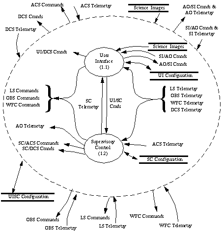
Comments on FIGURE 4-4., "Data Flow Diagram 1.0 - UI/SC"
FIGURE 4-5. Data Flow Diagram 1.1 - UI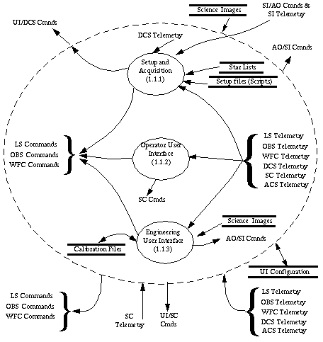
Comments on FIGURE 4-5., "Data Flow Diagram 1.1 - UI"
1.
2.
3.
FIGURE 4-6. Data Flow Diagram 1.1.1 - UI Setup and Acquisition
Comments on FIGURE 4-6., "Data Flow Diagram 1.1.1 - UI Setup and Acquisition"
1. We decided not to show any humans on this DFD, it is certainly understood that the human causes the events that in turn cause SKY or the handpaddle to take some action. The human is also the "destination" for any data flowing out of FACSUM.
2.
3.
FIGURE 4-7. Data Flow Diagram 1.1.2 - UI Operator User Interface 
Issues on FIGURE 4-7., "Data Flow Diagram 1.1.2 - UI Operator User Interface"
1. Note that the reason there are no output data flows drawn leaving the Exception Handling and Characterize &Optimize bubbles is that they result in informational displays only. The human is the intended destination of this information.
2.
FIGURE 4-8. Data Flow Diagram 1.1.2.1- UI Operator User Interface - Loop Control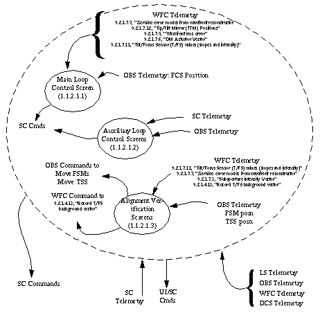
issues on FIGURE 4-8., "Data Flow Diagram 1.1.2.1- UI Operator User Interface - Loop Control"
1. Exactly which SC Commands are sent out of the loop control screen?
FIGURE 4-9. Data Flow Diagram 1.1.3 - UI Engineering User Interface
Issues onFIGURE 4-9., "Data Flow Diagram 1.1.3 - UI Engineering User Interface"
1. Is my view of the simulators as telemetry generators accurate?
2. What scripting tool allows both keyword control and image analysis?
3.
FIGURE 4-10. Data Flow Diagram 1.2 - Supervisory Control
Comments on FIGURE 4-10., "Data Flow Diagram 1.2 - Supervisory Control"
1. The divisions on this drawing are somewhat arbitrary. Some of the off-loading control loops and the compensation controls loops can be placed into either category. It is not the category that is significant.
2.'Process Cmnds' going into 1.2.3 could include DCS handshake commands like " DCS Requests permission to offset telescope", etc.
3. I don't see any LS commands coming out of any SC bubbles, is this right?
Also, no WFS or LS telemetry flowing into some SC bubbles?
3.
5.
FIGURE 4-11. Data Flow Diagram 1.2.1 - SC Off-loading Control Loops
issues on FIGURE 4-11., "Data Flow Diagram 1.2.1 - SC Off-loading Control Loops"
1.
2.
FIGURE 4-12. Data Flow Diagram 1.2.1.1 - SC Tilt Off-loading Control Loops (aka tilt off-loading from TTM to DCS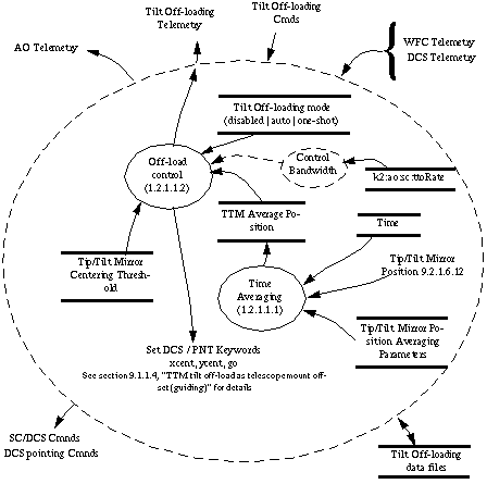 )
)
Comments on FIGURE 4-12., "Data Flow Diagram 1.2.1.1 - SC Tilt Off-loading Control Loops (aka tilt off-loading from TTM to DCS)".
The AO system will be able to provide the ACS with feedback about primary mirror segment errors. Each segment covers approximately 6 subapertures in the WFS. The time averaged data from those subapertures can be used to determine the tilt errors associated with each segment. These tilt errors will be sent to ACS for correction.
FIGURE 4-13. Data Flow Diagram 1.2.1.2 - SC Segment Tilt Off-loading Control Loop
Notes on FIGURE 4-13., "Data Flow Diagram 1.2.1.2 - SC Segment Tilt Off-loading Control Loop"
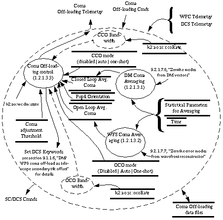
Notes on FIGURE 4-14., "Data Flow Diagram 1.2.1.3 - SC Coma Off-loading Control Loop"
FIGURE 4-15. Data Flow Diagram 1.2.1.4 - SC Off-loading Control Loops - focus sensor off-loading (LGS Mode) 
1. What frequency is this done at?
2. To allow maximum flexibility, this control loop can be run with or without a separate open loop focus correction for elevation dependence. What are the implications for the two focus corrections to FCS interfering with each other?
3. Should I mention the fact that this is used in LGS mode only?
4. Have I got this right? The EL dependence on LGS focus goes to the FCS and therefore is on this drawing?
5. Should I mention that the T/FS is looking at an NGS, just as a reminder?
6.
FIGURE 4-16. Data Flow Diagram 1.2.1.5 - SC Off-loading Control - WFS Focus Off-loading
Comments on FIGURE 4-16., "Data Flow Diagram 1.2.1.5 - SC Off-loading Control - WFS Focus Off-loading"
FIGURE 4-17. Data Flow Diagram 1.2.2 - SC compensation control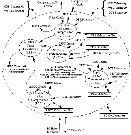
issues on FIGURE 4-17., "Data Flow Diagram 1.2.2 - SC compensation control"
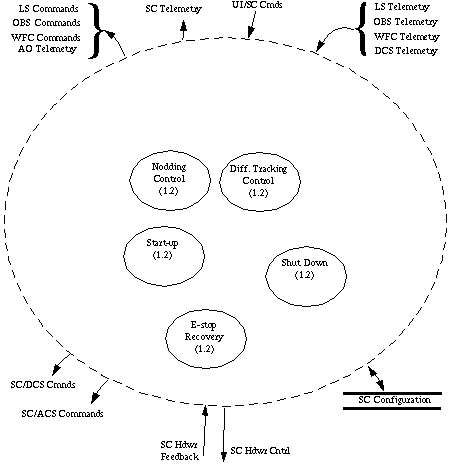
Comments on FIGURE 4-18., "Data Flow Diagram 1.2.3 - SC Process Control loops"
1. should there be a bubble labeled "self test", if not on this page, then where?
Should it be from the UI?
2.
3.
FIGURE 4-19. Data Flow Diagram 2.0 - OBS
issues on FIGURE 4-19., "Data Flow Diagram 2.0 - OBS"
1. We discussed several different ways of organizing the OBS data flow. One obvious way was to follow the same categories as used in some other documentation. (science path, wavefront sensing path, etc.). While that organization would certainly have it's benefits, the draw back was that it would have separated devices that seemed to belong together (for example the VDC and the IDC would have been in different categories.) We instead elected to group devices that were more similar in function and base our grouping less on bench geography.
Keep in mind that these divisions used are more for the convenience of drawing DFD's than they are for software architectural hierarchy.
2.
FIGURE 4-20. Data Flow Diagram 2.1 - OBS Rotational Tracking Devices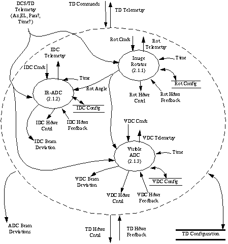
Comments on FIGURE 4-20., "Data Flow Diagram 2.1 - OBS Rotational Tracking Devices"
1. Time? It comes from OBS VME crate. But what about the time stamped demand? Should I show that as coming from somewhere else?
wlupton notes: I would show time stamp as coming with demand and current time ad direct input to mechanism; implication is that mechanism interpolates demand to current time [we have a generic EPICS interpolation record which should do the job.
2. How is image rotator position demand generated, and by whom. If it is calculated by the same code as currently used within the TCS, then it will automatically take into account the telescope anomalies.
wlupton notes: If DCS knows tracking mode "position angle" and generate rotator demands directly; this allows it to account for telescope imperfections, especially near zenith. It could send a corrected parallactic angle and the AO could co the calculation; not sure which is best...
FIGURE 4-21. Data Flow Diagram 2.2 - OBS Sensors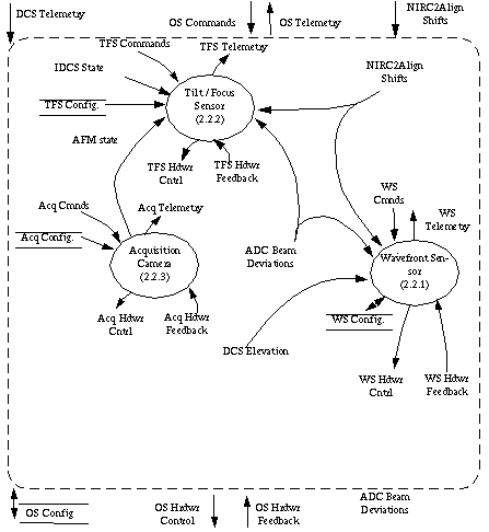
Comments on FIGURE 4-21., "Data Flow Diagram 2.2 - OBS Sensors"
1. Some of the devices on the OBS that might be considered 'sensors' are place in the Alignment, Calibration and Diagnostic section. The sensors on this DFD are those that are used as an integral part of AO system operation.
2. Wavefront Sensor in this context is much more than the GTRI wavefront sensing camera. Here it means the camera, it's focus stage, camera mounting stage,
3. Should I show TAT here? Time Avg. Tilt used for measuring nods.
FIGURE 4-22. Data Flow Diagram 2.3 - OBS Diagnostic Devices
Comments on FIGURE 4-22., "Data Flow Diagram 2.3 - OBS Diagnostic Devices"
1. Perhaps the telescope simulator should receive AZ/EL from DCS for the purpose of controlling the rotating pupil mask.
2.
FIGURE 4-23. Data Flow Diagram 2.4 - OBS Bench Setup
Issues on DFD FIGURE 4-23., "Data Flow Diagram 2.4 - OBS Bench Setup"
1. We made a conscious decision to put the IN/OUT motion of the IR ADC on this DFD. Note that the other 2 degrees of freedom are on diagram 2.1. rotatiional tracking devices. They are separated because obvious differences in use. The rotational degrees of freedom are used during closed loop operation, and the in/out degree of freedom is only used during bench set-up.
2.
FIGURE 4-24. Data Flow Diagram 2.2.1 - OBS Sensors - Wavefront Sensing
Questions on FIGURE 4-24., "Data Flow Diagram 2.2.1 - OBS Sensors - Wavefront Sensing"

Comments on FIGURE 4-25., "Data Flow Diagram 2.2.1.5 - OBS Sensors - Wavefront Sensing Setup"

Notes on FIGURE 4-26., "DFD 2.2.2 OBS Sensor - Tilt/Focus"
1. The TSS config file set must include the field dependent error correction calibration file.
2. The Neutral Density Filter wheel is not shown on this drawing. Remember that it is under the control of the WFC, but through the UISC/WFC interface, we have some measure of control. Probably that control will come from the SC though, not really from the OBS computer.
3. "enable field dependent error corrections" should come over the command line. Remember to include it.
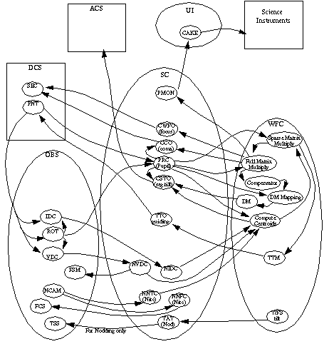
Issues on FIGURE 4-27., "Data Flow Diagram for NGS Closed Loop Operation"

Comments on FIGURE 4-28., "Data Flow Diagram for closed loop LGS operation"
| Library Name | Files list |
|---|---|
| AO Configuration | |
| .......LS Configuration Files | |
| ........OBS Configuration Files | |
| Diagnostic (Diag.) Configuration | |
| Tracking Devices (TD) Configuration | |
| Sensor Component (OS) Configuration | |
| ........UISC Configuration Files | |
| ........WFC Configuration Files | |
Generated with Harlequin WebMaker