7.0 IMPLEMENTATION
state) and in a numeric form (stateVal).
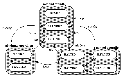
FIGURE 7-1. Keck II standard state model
In general, high-level subsystem control code can be thought of as executing a state machine. Depending on the details of the subsystem there will often be other lower-level state machines executing within the subsystem. The subsystem state can be thought of as a compendium of the lower-level states. Later on, some more specific examples of this will be given in the context of the SC and OBS subsystems.
Refer to Ref. 1 for details of the Keck II standard state model, a diagram of which is reproduced in Figure 7-1 on page 7-2. The "init and standby" and "abnormal operation" states and transitions should be adhered to by all subsystems, but the "normal operation" states will of course vary widely between subsystems. The same document also introduces the "three state-set" model that has been developed for the Keck II DCS. In this model, each sequence implements three independent state transition diagrams (each of which is a VxWorks task):
Generated with Harlequin WebMaker