Elevation Limits Due to Pupil Rotation
Introduction
|
The Keck 2 laser projection telescope is located along the side of the
telescope, 6.2 m from the optical axis, and illuminates a cylinder of
Na atoms in the Earth's mesosphere approximately 1 m diameter and 10 km long.
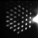
The apparent elongation of the laser guide star (LGS) therefore varies
across the pupil, reaching ~3.5" at the edge farthest from the projection
telescope (see Fig. 1).
This elongation pattern remains fixed to the telescope pupil, but
varies with the elevation of the telescope and the changing structure
of the Na layer.
|

Fig 1: LGS with primary unstacked
|
As the LGS is observed by the wavefront sensor (WFS) quad cells, the
elongation of the spots induces quasi-static aberrations in the corrected
wavefront.
The LGS aberrations are sensed by the low-bandwidth wavefront sensor (LBWFS),
and corrected by changing the centroid locations to which the spots on
the WFS are driven.
For targets with sufficiently bright TT references (R<16.0), this dynamic
image sharpening is performed continuously during observations.
We are currently developing a predictive model of the LGS aberrations,
for use on targets with TT references R>16.0, but this has not yet
been implemented.
Maximum acceptable pupil rotation rate
When observing in position angle mode (PA fixed on NIRC2), the telescope
pupil and LGS elongation pattern will appear to rotate on the WFS.
If this rotation is faster than the rate at which we can measure and
correct the LGS aberrations, the image quality will suffer.
The WFS centroid correction is an iterative process, and ~5 iterations
are required to reach convergence.
| R magnitude |
LBWFS integ. (s) |
Convergence (s) |
| 14.0 |
20 |
100 |
| 15.0 |
30 |
150 |
| 16.0 |
45 |
225 |
Table 1: LBWFS convergence time vs. TT reference R mag.
The convergence times listed in Table 1 must be compared with the pupil
rotation rate for a given target and the critical rotation angle at which
the error in the estimate of the LGS aberrations becomes dominant.
Near zenith, 5° pupil rotation will induce a 100 nm wavefront error,
while 10° pupil rotation leads to 200 nm of wavefront error.
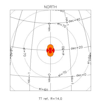
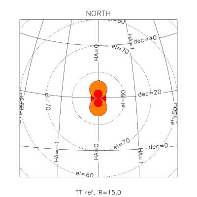
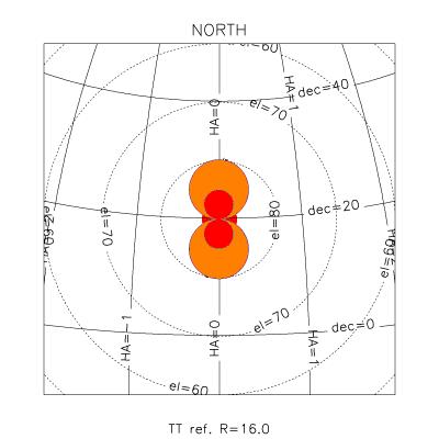
Figures 2-4 show the region of the sky over which the pupil rotation
rate is low enough to allow correction of the LGS aberrations, for
TT reference stars R=14,15,16.
Orange and red zones mark the regions in which >100 nm and >200 nm of
LGS aberrations should be expected.
The red region at el>87° represents the "keyhole" region excluded
due to telescope azimuth tracking constraints.
Depending on the declination of the target, passage through the region
of poor correction can last up to 50 minutes (for an R=16.0 TT
reference).

Fig 2: R=14.0 TT ref
|

Fig 3: R=15.0 TT ref
|

Fig 4: R=16.0 TT ref
|
. |