How to interpret effects of rotator on pupil and image
Introduction
The rotator misalignments have two components.
- An external misalignment that occurs when the optical axis of the rotator is misaligned with respect to the input beam. The external misalignment induces a circular displacement of pupil and image whose period is half the rotator period.
- An internal misalignment that occurs when one of the internal mirror of the rotator is out of alignment. The internal misalignment induces a circular displacement of the pupil and image whose period is the same as the rotator period.
In order to properly analyze a global misalignment of the rotator, one needs to disentangle internal and external misalignments. Taking pairs of measurements of the pupil or image 180deg apart does it. Half the difference between 180deg-apart measurements gives the internal misalignment.
IDL tools
IDL tools where developed to analyze the pupil displacement measured with the AO WFS in pupil imaging mode and the image displacement measured with the AO ACAM. Both pupil and image data must be properly ordered and stick to the following rules:
- You must take 2N data.
- Data i and i+N must be taken 180deg-apart.
- Data 0 must be taken at always the same rotator angle if you want to follow the evolution of errors.
If you take only two sets of data 180deg apart, even if you are able to compute the internal misalignment, it is not enough to compute the external misalignment. In general a minimal measurement set should look like [-180, -90, 0, 90] if you are interested in internal and external misalignments, and should look like [-180,0] if the internal misalignment is sufficient.
Pupil measurements
PRO RotatorError_WfsPupil, DiagPath, DiagNb,
IntErr=IntErr, ExtErr=ExtErr, SHOW=show
This procedure computes the internal and external error on the pupil.
DiagPath: the path to the WFS diagnostic files to use.
DiagNb: the array of the diagnostic files to be used for the internal/external measurements.
IntErr: a keyword used to output the result of the internal misalignment, calculated for the first diagnostic file. If a non-initialized variable is passed, the current measurement is assigned to the keyword. If there is a previous result in the variable the current measurement is added to it. This is to monitor the evolution of the internal misalignment.
ExtErr: is for the external error with the same behavior as for the internal error.
Show: see next figure.
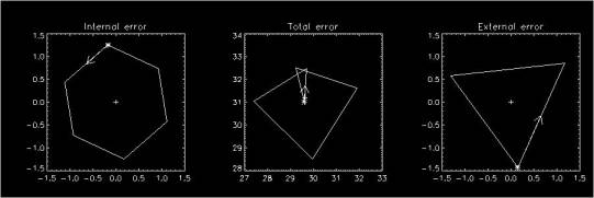
This is the output of RotatorError_WfsPupil when SHOW keyword is set. Diagnostic files where obtained for the following rotator angle: [-180,-120,-60,0,60,120]. The star corresponds to the –180deg measurement and is the one that will be returned to the user through IntErr and ExtErr keywords. The arrow indicates the direction of the measurement-to-measurement direction. The cross indicates the center of the measurements. The result was obtained with the following code.
RotatorError_WfsPupil,
'J:\nightly2\04\02\20\', [7,8,9,10,11,12], /show
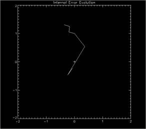
This illustrates the evolution of the internal error through 7 sets of measurements as an internal mirror of the rotator was adjusted. The result was obtained with the following code.
DELVAR,
IntErr
RotatorError_WfsPupil,
'J:\nightly2\04\02\20\', [0,1,2,3,4,5], interr=interr
RotatorError_WfsPupil,
'J:\nightly2\04\02\20\', [7,8,9,10,11,12], interr=interr
RotatorError_WfsPupil,
'J:\nightly2\04\02\20\', [13,14,15,16,17,18], interr=interr
RotatorError_WfsPupil,
'J:\nightly2\04\02\20\', [19,20], interr=interr
RotatorError_WfsPupil,
'J:\nightly2\04\02\20\', [21,22], interr=interr
RotatorError_WfsPupil,
'J:\nightly2\04\02\20\', [23,24], interr=interr
RotatorError_WfsPupil,
'J:\nightly2\04\02\20\', [25,26], interr=interr
PLOT,
IntErr[0,*], IntErr[1,*]
For the first three data sets, 6 measurements 60deg apart are used, and then only 180deg apart.