Interfacing Visitor Instruments at the Keck II F/40 Bent Cassegrain Port
2.0 F/40 Optical Description 4
3.0 Infrared Fast Steering Mechanism (IFSM) 5
7.0 Mechanical Constraints on Visitor Instrument 8
9.2 Interfacing via Ethernet 13
9.3 Interfacing via Serial Cable 13
10.0 Instrument Cooling System 13
1.0 Introduction
A facility was commissioned in late 1997/early 1998 for visitor science instruments at the f/40 bent Cassegrain focus of the Keck II telescope. The major feature of this focus is that it uses an infrared-optimized secondary mirror mounted on a chopping mechanism. The facility includes a rotator on which to mount the visitor instrument and an off-axis guider camera, as well as electrical and cooling interfaces.
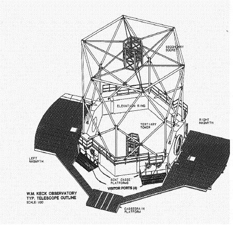
The physical location of this visitor port on the telescope is shown in Figure 1. Figures 2 and 3 show the first visiting instrument to be used at the visitor port, MIRLIN.
-
FIGURE 1. Perspective view of the telescope. The bent Cassegrain ports are indicated. The instrument port is the second one from the right Nasmyth platform.

-
FIGURE 2. The visiting instrument MIRLIN mounted on the visitor's port. The white rack attached to the platform rails on the left side of the photo contains guider electronics. Next to it, behind the vertical white rail, is teh instrument's off-rotator electronics rack, with cables leading to the on-rotator electronics box to the right and slightly below the gold dewar. This and the following photo provided by Joel Aycock.

-
FIGURE 3. A closer view of MIRLIN on the visitor's port shows the large sweeping aluminum shield for the cable wrap (not currently in use). The guide camera is the aluminum box located below and left of the gold dewar in this photo (at "6 o'clock" on the rotator). The round instrument mounting flange peeks out to the left of the rectangular instrument mounting plate; the latter provided by the instrument group.
2.0 F/40 Optical Description
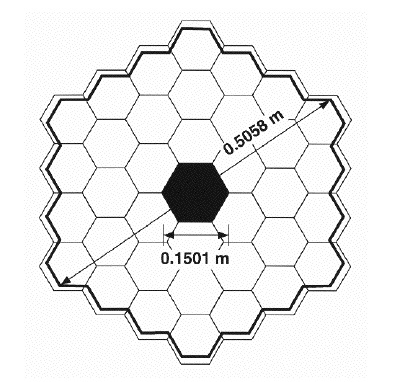
The optical path includes the primary, secondary, and tertiary mirrors. The primary and tertiary mirrors are optically polished Zerodur with aluminum coatings (with future plans to silver these mirrors), and the secondary is diamond-turned electroless nickel on beryllium with a gold coating. The primary mirror has a circumscribed diameter of 10.949 m with a radius of curvature of 34.974 m and a conic constant of -1.003683. The primary to secondary mirror distance is 16.640 m. The secondary mirror (radius of curvature = -1.771 m, conic constant = -1.28080) is undersized by about 95.4% (see Figure 4) and is therefore the stop for the system. The central hole in the secondary is oversized by 120%, assuring that instruments can receive light only from the night sky.The tertiary mirror is a flat which folds the f/40 beam by 90 deg to the bent Cassegrain focus. The distance from the tertiary to the optimal focal plane is 6.500 m. The instrument mounting surface is located 162 mm in front of the optimal focal plane.
-
FIGURE 4. The secondary mirror (heavy line) is shown with the image of the primary segments (light lines) superimposed. To protect against excess background light entering mid-IR instruments, the secondary is undersized by a factor of 0.954, with a central hole oversized with respect to the primary's central hole.
The f/40 focal length is 395.0 m producing a plate scale of 1.915 mm/arcsec or 0.522 arcsec/mm. The focal plane is curved toward the secondary mirror with a radius of curvature of 0.85 m.
The exit pupil is located at the secondary mirror, 19.14 m in front of the focal plane with a circumscribed diameter of 0.5058 m.
The field of view is limited by the inner diameter of the mounting plate to a diameter of 357 mm corresponding to 186 arcsec. However the pick off mirror for the guider intrudes upon this area (section 5).
A 1.70 mm displacement of the secondary mirror from the optimal position will shift the focal plane by 837 mm resulting in an rms image diameter due to spherical aberration of 0.10 arcsec on-axis and total aberrations 0.26 arcsec at a field radius of 2.5 arcmin.
Coma on axis may arise if the optical axis of the secondary is not coincident with the optical axis of the primary. It can be removed (on axis) by shimming and/or tilting the secondary. The first technique requires careful characterization and analysis, followed by a day's work in doing the shimming. Tilting the secondary, however, can be accomplished at night using an observational technique called "MAlign," which accurately measures the coma and optimum focus by spreading the segments of the primary mirror known amounts and measuring their relative shifts. MAlign can be used on either the guider or the science detector, taking roughly five to ten minutes of sky time.
3.0 Infrared Fast Steering Mechanism (IFSM)
The secondary mirror is mounted on the IFSM which was designed for fast steering applications and which offers some limited chopping capabilities.
The actuator mechanical limit is ~30 arcsec on the sky. The scale factor between tilt on the mirror and tilt on the sky is 10.32. Figure 5 is a plot of chop frequency, f, versus angle on the sky, t (in arcsec). The nominal chopping requirement is shown as 2 arcsec on the sky at 10 Hz with an 80% duty cycle,  , using a power P = 1.3 W. The 6 W curve represents a theoretical maximum we could achieve with various hardware and software upgrades to the system, but these upgrades are not planned at this point in time. The formula used to generate these curves is:

In fact, the actual performance of the IFSM has been shown to be somewhat worse than this curve, especially at large chopper throws. Work to improve the performance continues.

4.0 Rotator
The rotator is controlled via a closed position loop using an incremental encoder. Encoder resolution is 0.3 arcsec. The rotational accuracy during tracking is 15 arcsec rms. The slew rate is 2 deg/sec. Control is via the telescope's Drive and Control System (DCS). The rotator can rotate over a range of 505°.
Accuracy and repeatability of the rotator was tested during engineering time by imaging a crowded star field at various rotator position angles. Both the absolute accuracy (within an overall zero point which was calibrated using astrometric doubles) and repeatability were better than 0.02°, which is approximately the uncertainty in the measurements themselves.
5.0 Guider
The camera is an unfiltered Photometrics PXL CCD camera with 1024x1024 pixels. The maximum guide rate expected from this camera is around 1-2 Hz. During engineering tests in 1997 December and 1998 January, image quality was checked by spreading the 36 segments of the Keck II primary out, so that the stars formed 36 well-separated images. The table below summarizes measurements of images taken in this mode, and indicates excellent optical image quality.
| Date |
Number of images |
Average segment (FWHM in arcsec) |
Best Segment (FWHM in arcsec) |
|---|---|---|---|
| 97/12/12 | 10 | 0.69 | 0.64 |
| 97/12/15 | 2 | 0.47 | 0.40 |
| 97/12/15 | 4 | 0.39 | 0.28 |
| 98/1/14 | 2 | 0.35 | 0.28 |
| 98/1/14 | 2 | 0.38 | 0.31 |
| average: | 0.46 | 0.38 | |
| median: | 0.39 | 0.31 |
The guider optical path consists of a fold mirror, a field lens (Melles Griot LDX 235) and a Nikon reimaging lens (EL-Nikkor 50 mm f/2.8). The fold mirror is located 161.5 mm or 84 arcsec off-axis providing a circular field of view to the camera of ~ 50 arcsec diameter. The plate scale on the guider camera is 0.0513 arcsec/pixel; 2x2 pixel on-chip binning is used to change the effective scale to 0.1026 arcsec/binned pixel. 4x4 binning may also be used to advantage in some cases. The "gain" of the guiding algorithm is set to 0.4, meaning that for a given detected centroid error, a correction only 40% as large will be made. This helps keep the autoguider system from unstable oscillations, as does a 1 Hz upper limit to the update rate.
The guider is nominally located at the optimal telescope focus, although it can be manually repositioned to allow the science instrument focal plane to be shifted over the range from 123 to 273 mm with respect to the instrument mounting surface. It cannot be repositioned in real time.
The guider camera unit is attached to the rotator so that it can sweep out a total area of 7.3 square arcmin. The probability of finding no guide stars is given by the equation P(0) = exp(-rA), where r is the star density and A is the field of view. Assuming a 19th magnitude limit, with r = 1157 stars/deg2 at the galactic pole and A = 0.002 deg2, gives a probability for finding no guide star of 0.10. Note however that dewar orientation constraints may make available only 180° of rotation, increasing the probability of finding no guide stars to 0.30 at the galactic poles. On the other hand, lower galactic latitudes generally provide significantly more guide stars than the poles.
The Keck guider system provides a user interface and control software for acquisition, guiding, offsetting while guiding, compensation for field rotation, dispersion correction, and automatic centering of the telescope. User procedures can also access a few of the more fundamental guider functions via a keyword layer. The Keck Observing Assistants (OAs) will generally operate the guider software for the observers.
6.0 Mechanical Interfaces
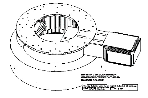
The instrument mounting surface has two different tapped bolt hole patterns available as shown in Figure 6, which shows the entire rotator mechanism. These patterns were chosen to be identical to those offered for visitor instruments at the IRTF. Bolt pattern #1 consists of seven 1/2-13 bolts at +/- (15°, 60°, 120°, and 180°) from vertical on an 18-inch diameter circle. Pattern #2 consists of twelve 3/8-16 bolts at +/- (15°, 45°, 75°, 105°, 135°, and 165°) from vertical on a 24-inch diameter circle. The latter, symmetric pattern allows the instrument to be bolted on in a variety of orientations, which could be useful when full consideration of orientation effects on the dewar are taken into account. We recommend the symmetric pattern if possible.
7.0 Mechanical Constraints on Visitor Instrument
The maximum allowable instrument weight is 1000 kg, the maximum bending moment is 470 kg- m, and the maximum rotational moment is 7900 kg m2. The instrument should be rotationally balanced to within 12 kg m2 s-2. The instrument must fit within a cylinder, with maximum diameter of 1.75 m, and maximum length along the rotational axis of 1.0 m. The instrument cannot extend in towards the telescope's tertiary mirror past the mounting surface, otherwise it will interfere with the guide camera and its light path.
The focal plane for the visitor instrument should be located between 123 and 273 mm from the mounting surface, as determined by the manual range in guider camera focus. The optimal focal position, defined by on-axis aberrations, is 162 mm behind the mounting plate.
8.0 Electrical Interfaces
The following general purpose instrumentation cables (type and quantity) are terminated at an Instrument Interconnect Panel located next to the visitor port, and at the Instrument Interconnect Rack (IIR) located in the computer room, next to the control room: eight coax, ten twisted pairs (all contained within one Bendix PT025E2461P96 connector), and ten fiber optic cables. There are also clean and commercial 120 V outlets available. Note that we do not have requirements on power dissipation in the dome for visiting instruments; however too much heat that close to the primary mirror can clearly affect image quality. For Keck facility instruments, our power dissipation requirement is 100 W, while our goal is 50 W. Excess heat in facility instruments is carried away using the glycol lines.

-
FIGURE 7. Diagram of the interconnect panel at the RBC port on the telescope. Note that all twisted pairs run over the J10 connector.
A cable wrap was originally designed to accomodate cables coming off the rotator to either the instrument interconnect panel or a user supplied rack located on the bent Cassegrain platform. This cable wrap is shown in Figure 7. However, the cable wrap in its original incarnation did not work well. Until the cable wrap is completed we are asking visiting instruments to provide a means of carrying the instrument and guider cables and coolant lines off the rotator, along the axis of rotation. This generally takes the form of a tripod arrangement with a collar on the axis.

-
FIGURE 8. Front view of the bent Cassegrain port showing the cable wrap at two rotator position angles.

9.0 Computer Interfaces
Visitor instruments have a choice of interfacing with the telescope via either ethernet or a serial cable. The following is only an overview of the procedures. Details needed to implement and test a visitor interface are available on the CARA intranet in "Software Interfaces for Visitor Instruments" ( http://www.keck.hawaii.edu/vis/index.html ). For access to this page contact webmaster@keck.hawaii.edu .
9.1 Command Examples
This section contains examples of only the most common telescope and chopper commands. For a complete list of possible keyword commands, visit the internal page referenced in section 9.0 above.
If the home institution of the visiting team has ethernet access to a Sun workstation running SunOS, Keck can provide a telescope simulator for testing scripts before the visit. We also have available a laptop simulator which can be loaned out to visiting instrument teams. Providing the simulator on systems other than SunOS, most notably Solaris, is in the works.
As with most Keck subsystems, a user controls and monitors the telescope by writing and reading keywords. Keywords are in essence "hooks" into the control software that allow the user to manipulate relevant parameters. They are written using the "modify" command and read via the "show" command. These are often aliased to the letters "m" and "s" for convenience. Some examples are given below; note that "dcs2" stands for the "Drive Control System" for Keck II, and "chp" stands for the chopper system. DCS keywords are detailed in Keck Software Document 46 (KSD46). Keep in mind that the user can write "scripts," containing multiple telescope, instrument, and/or chopper commands, allowing sophisticated observing routines to be accomplished with a small number of scripts.
9.1.1 Focusing
To piston the secondary, issue the command
m dcs2.telfocus=X
where X is the position in millimeters. The best known focus is generally near zero, and the secondary has a range of approximately 50 mm. A 0.1 mm shift in the secondary moves the f/40 focal plane by ~49 mm.
9.1.2 Offsetting
To offset the telescope, issue the command
m dcs.raoff=X dcs.decoff=Y rel2curr=t
where X and Y are offsets in R.A. and Dec. in arcsec. The offset is cumulative when rel2curr=t is used, so for example the two successive commands
m dcs.raoff=0.1 dcs.decoff=0.3 rel2curr=t
m dcs.raoff=0.1 dcs.decoff=-0.2 rel2curr=t
will result in a net offset of 0.2 arcsec north and 0.1 arcsec east.
To "zero out" the offsets (i.e. return to the "base" position), use
m dcs.raoff=0 dcs.decoff=0 rel2curr=f
Whenever the operator acquires a new object, the cumulative offset is automatically reset to zero.
9.1.3 Chopping
To set up the chopper to chop in "continuous" mode (no external trigger) at Z Hz, with a throw of Y arcsec at p.a. X deg, issue the command
m chp.chpfreq=Z chp.chpamp=Y chp.chpang=X chp.chprelto="posang" chp.chptrig="disabled" \
chp.chpon=t
Most chopping will use a TTL signal provided by the instrument:
m chp.chpfreq=Z chp.chpamp=Y chp.chpang=X chp.chprelto=posang chp.chptrig=level \
chp.chpon=t
Note that even though the instrument is providing the chopping trigger in the latter case, an estimate of the chopper frequency (Z) is still specified, so that the chopper's error correction algorithm will be able to anticipate the incoming chop trigger with some accuracy. In all cases, to stop chopping use the command
m chp.chpon=f
(For a complete description of chopper keywords and their function, see KSD78.)
9.2 Interfacing via Ethernet
The Observatory provides a thinnet cable (coax T-connector) to which the ethernet adaptor on your computer can be connected. Details such as IP numbers, broadcast addresses, and netmasks are specified on the internal page referenced above.
If the instrument computer resides in the control room, the connection is straightforward. If, however, the instrument control computer is located on the telescope itself, then cable length, noise, and accessibility must be considered.
Once the instrument computer has been connected and can "ping" the telescope host computer, commands can be sent over ethernet via any of the following protocols: direct socket connection, remote command execution (e.g. rsh), or ftp. These are given in the order of preference. All are preferred over the serial connection described in the next section. Details of the three methods are documented on the internal page.
9.3 Interfacing via Serial Cable
The Observatory provides an RS-232 serial cable to which the serial port on your computer can be connected. Details of the pinouts, null modems, stop bits, and baud rate are given in the internal page.
If the instrument computer resides in the control room, the connection is straightforward. If, however, the instrument control computer is located at the telescope focus, then cable length, noise, and accessibility must be considered.
9.4 The guider
The guider is controlled by the Observing Assistant using the "xguide" tool. When the telescope receives a move command, the guide box can either move with the stars if possible, allowing guiding to continue on the same guide star assuming that star remains on the field (offset mode), or the guide box can stay put (chop-nod mode), depending on whether the NODTEL keyword is off or on, respectively. Note that in the latter case, a slight "tail" from the chop may affect the guide star centroid, and if so it will affect guiding in the two nod cycles differently. Hence when using "chop-nod" mode, it may be advantageous to include a slight telescope offset to remove this guiding bias.
10.0 Instrument Cooling System
Coolant, a mixture of 70% water and 30% ethylene glycol, is piped in insulated tubing to all the various instrument locations and to the socket for the secondary mirrors (where it is used with the chopping secondary). The coolant's freezing point is -15 C. The mixture has a specific heat of 3611 J/kg K (0.8625 Btu/lb R) and a density of 1093 kg/m3 (68.3 lb/ft3).
Typical operating pressure at the Nasmyth deck level is 345 to 415 kPa (50 to 60 psig). Maximum system pressure at the bent Cassegrain instrument connect panel with the telescope at the zenith is 550 kPa (80 psig). The instrument plumbing should be able to withstand a pressure of 620 kPa (90 psig). There is a differential pressure regulator between the supply and return connectors at each panel. The differential pressure is adjustable, and is typically set at 275 kPa (40 psi).
The design flow rate to each of the bent Cassegrain instrument connect panels is 4.9 lpm (1.3 gpm). For all other instrument connect panels it is 9.8 lpm (2.6 gpm). Coolant flow is continuous, except in the case of equipment failure or power outage.
The coolant temperature is 3 C below the dome ambient air temperature. Typical range of the coolant temperature is -10 C to 0 C. The temperature rise of coolant through the instrument should not be more than 3 C. The heat load from instruments at the bent Cassegrain positions should not exceed 1000 watt; at other positions it should not exceed 2000 watt.
Fittings on the instrument connect panels are 1/2-inch Parker FS-500 series quick connect couplers. The instrument coupler on the supply side should be male (Parker FS-502-8FP), and the return coupler should be female (Parker FS-501-8FP).
We recommend the instrument have the following provisions:
- Heat exchanger(s) and air circulation as required.
- Sufficient insulation to limit heat loss into the dome to less than 100 watts to minimize seeing degradation.
- An adjustable flow control valve to establish the correct temperature rise in the coolant.
- Temperature sensors at critical points with provision to shut down equipment in the event of overheating.
- A flow sensor in the coolant supply line to shut down critical equipment if flow is lost. Liquid nitrogen or helium fills can be performed using a CARA supplied dewar which is rolled onto the adjacent Nasmyth platform.
11.0 Science Instruments
Several potential visitor science instruments were considered, as well as the IRTF interface document, during the design of the bent Cass visitor port in order to determine whether the design could accomodate a variety of instruments. Accepted visitor instruments are shown below. A list of important compatability criteria was developed, and is available as a questionnaire, and is summarized in the last table . In this last table note that some of the criteria have optimal values, some have ranges or limits, and some are meant more as information for the instrument builder or for us.
| Instrument | Description | P.I. |
| MIRLIN | mid-IR imager | Mike Werner and Mike Ressler, JPL |
| OSCIR | mid-IR imager and spectrograph | Charles Telesco, Univ. of Florida |
| Instruments accepted but not commissioned | ||
| MIRAC2 | mid-IR imager | Bill Hoffman, Univ. of Arizona |
| KWIC | 12-40 micron imaging Fabry-Perot | Gordon Stacey, Cornell Univ. |
| Optimal Value | Range | |
| Focal ratio | f/40 | |
| Expected exit pupil position (in front of focal plane) | 19.14 m | |
| Distance from mounting surface to focal plane | 162 mm | 123-273 mm |
| Field of view | 186 arcsec | |
| Mass | 1000 kg | |
| Bending moment | 470 kg m | |
| Rotational moment | 7900 kg/m2 | |
| Out-of-balance moment | 12 kg/m2/s2 | |
| Diameter | 1.75 m | |
| Length | 1.0 m | |
| Required cabling through telescope cable wrap: | ||
| coax | 4 | |
| RS-422 | 10 | |
| fiber optic | 10 | |
| Cable length through wrap | 100 m | |
| Dimensions of electronics rack on telescope | ||
| Length of cable between instrument and nearby electronics rack | ||
| Computer interface | ethernet (thinnet) or serial | |
| Cooling requirements: | ||
| glycol | 4.9 l/min | |
| LN2 | ||
| LHe | ||
| Electrical power requirements (commercial and clean) | ||
| Chopping requirements (for proposal) | 2 arcsec @ 10 Hz | 30 arcsec |
| Mounting hole pattern #1: 18 in (457.2 mm) diameter pattern, 1/2-13 bolts at 7 locations, (15°, 60°, 120°, 180°) from vertical | ||
| Mounting hole pattern #2: 24 in (610 mm) diameter bolt pattern, 3/8-16 bols at 12 locations, (15°, 45°, 75°, 105°, 135°, 165°) from vertical | recommended | |