 Figure 1: A spectral image from NIRSPEC
 NIRSPEC Instrument and Data Format*
1. NIRSPEC Overview
1.1 What is NIRSPEC?
NIRSPEC is an all-reflective, near-infrared, high-resolution spectrograph for the Keck II Telescope which is designed to operate over the wavelength region 0.95 to 5.4 microns. To cover this wavelength range efficiently at high spectral resolution, the instrument uses a cross-dispersed echelle grating and is therefore an infrared analog to HIRES. Unlike its optical counterpart however, NIRSPEC is a vacuum-cryogenic instrument operating at about 60 K.
Figure 1: A spectral image from NIRSPEC
In normal use, NIRSPEC will be mounted on the Right f/15 Nasmyth platform of the Keck II 10-meter telescope. It can also be located behind the Adaptive Optics system on the Left Nasmyth platform, but it is not optimized for AO. For its primary spectrographic detector, NIRSPEC employs an indium antimonide (InSb) array with 1024x1024 pixels from Raytheon-SBRC, but there is also an infrared slit-viewing camera (SCAM) with a field of view of 46x46 arcseconds and a pixel scale of 0.18"/pixel. This camera utilizes a mercury-cadmium-telluride (HgCdTe) infrared array with 256x256 pixels and a cut-off wavelength of 2.5 microns. The SCAM shares the same filters as the spectrograph optics. In addition, NIRSPEC has a CCD camera which can image the annular field around the SCAM field onto a 1024x1024 SITe chip. Either camera can be used for guiding.
In the dispersion direction at high resolution – the Echelle mode – each pixel represents 0.144 arcseconds and the resolving power is R ~ 25,000 (12 km/s) for an entrance slit of 0.43 arcseconds (3 pixels) width. Since NIRSPEC contains a single echelle grating and a single cross-disperser, about 25 grating settings are required to span the entire wavelength range (with overlaps) in Echelle mode. Only in the NIRSPEC-1 band at 1.07 micron does almost all of the free spectral range of each order fall on the detector. In other bands the echellogram overfills the 1024x1024 array.
There is also a Low Resolution mode covering the same wavelength range at R ~ 2,200 (for 2 pixels) in only a few (7) settings. One pixel in this low-resolution mode corresponds to 0.19" in the dispersion direction. The scale along the slit length (spatial direction) is 0.198 arcseconds per pixel and 0.143 arcseconds per pixel in the high- and low- resolution modes, respectively; this difference is the result of the TMA camera which has a different focal length for the two orthogonal directions.
A small selection of slit widths is available (see next section), and slit lengths are either 12" or 24" in the Echelle mode, or 42" in the Low Resolution mode. NIRSPEC includes a cryogenic image rotator for selecting position angles and for removal of field rotation. There is also a built-in Calibration Unit with four arc lamps and a white light source.
The astronomer can control NIRSPEC by means of a Graphical User Interface (GUI) and Echelle Format Simulator (or EFS). The EFS allows the user to visualize the expected layout of cross-dispersed spectral orders (the "echellogram") for any possible setting of the instrument. Each set-up can be stored and the program can also create observing "scripts" which can be executed to drive the instrument and collect data. Status information, e.g. the position of gratings or filter wheels, or the time remaining on the exposure, or the detector temperatures, or information about the calibration/guider unit, are all shown on special screens. Images from either the spectrograph or the SCAM are displayed using an IDL-based Quick Look package.
Access to the right (f/15) Nasmyth focal station of Keck II is shared with DEIMOS. In normal operation, NIRSPEC will remain cold and powered-up even when it is in its parked position on the Nasmyth platform. It is expected that DEIMOS and NIRSPEC will alternate at the focus every two weeks.
1.2 NIRSPEC’s Features
Section 1.4 contains a more detailed technical description of the instrument. Briefly, the f/15 focus is re-imaged at f/10 onto the slit plane inside the instrument. Re-imaging involves collimation and therefore provides a location for a Lyot stop and filters. The collimator section is essentially a rotating K-mirror which provides field rotation at the slit plane. A selection of slits with fixed lengths and widths are mounted in a wheel. Each slit is tilted so that the surrounding field can be viewed with an infrared camera. After the slit plane, the diverging f/10 beam is collimated at 120 mm onto the 22 l/mm echelle grating, used in quasi-Littrow mode, which is followed by a 75 l/mm cross-disperser grating. Finally, the beam is re-imaged at f/3 onto the InSb detector with a Three-Mirror Anastigmat (TMA) camera. A flat mirror can replace the echelle grating to provide a lower resolution mode in which dispersion is due only to the cross disperser grating. Apart from three lenses used with the slit-viewing camera, NIRSPEC’s optical design is fully reflecting and therefore achromatic. Each mirror is diamond-turned on nickel-aluminum with a post-polished finish for low scatter and a high-reflectivity coating of Denton FSS99 silver.
NIRSPEC has three basic modes:
In the High Resolution mode, both the echelle grating and the cross disperser are used to produce a complete echellogram. In the Low Resolution mode, the echelle grating is replaced with a flat mirror so that the spectrum is produced only by the cross dispersion grating. In imaging mode, the light is not dispersed at all, and the field is imaged onto the detector.
Table 1 provides a summary of these modes, options and features of NIRSPEC.
Table 1 Modes
| High Resolution Echelle Spectroscopy | Wavelength range: 0.95-5.4 microns, R = 25,000 for 0.43" slit (3 pixels). Slit lengths of 12" or 24" |
| Low Resolution Spectroscopy | Wavelength range 0.95-5.4 microns, R = 2,200 for 0.38" slit (2 pixels). Slit length of 42" |
| Near Infrared Imaging (SCAM) |
Wavelength range 0.95-2.5 microns, FOV = 46" x 46"; Pixel scale = 0.183"/pixel |
Rather than providing a cryogenic mechanism to give arbitrary slit widths, NIRSPEC employs a selection of fixed slit widths, in two lengths for the echelle mode, and a single longer length for the low-resolution mode. The orientation of each slit on the sky is different, but these values are coded into the software. A dual filter wheel in the collimated beam provides a selection of order-sorting filters, blocking filters, narrow-band filters and Lyot stops. Table 2 gives a summary of NIRSPEC’s properties and design parameters.
Table 2 Summary of Properties
|
PROPERTY |
ECHELLE MODE |
LOW RESOLUTION MODE |
|
Wavelength Range |
0.95 - 5.4 micron |
0.95 - 5.4 micron |
|
Number of settings required |
25 |
7 |
|
Pixel scale (along dispersion) |
0.144"/pix |
0.193"/pix |
|
Resolving Power (0.42" slit) |
23,640 |
2,264 |
|
Slits Widths |
0.14, 0.29, 0.43, 0.58, 0.72" |
0.38, 0.57, 0.76" |
|
Slit Lengths |
12" or 24" |
42" |
|
Groove Density |
23.2 l/mm |
75 l/mm |
|
Blaze Angle/Gamma Angle |
63.5° /5.0° |
10° /0° |
|
Collimated Beam Width |
120 mm |
120 mm |
NIRSPEC has seven custom-designed blocking filters (named NIRSPEC-1 through 7) which completely cover the 0.95-2.6 micron region. There are standard K and K', L', and M' filters together with two special "wide" filters called KL (2.16-4.19 micron) and Mwide(4.40-5.60 micron). Note that NIRSPEC-3 and NIRPSEC-5 approximate J and H. Six narrow band filters (about 1% wide) are included namely, HeI (1.083), Paschen Beta (1.282), [FeII] (1.644), H2 (2.121), Brackett Gamma (2.165), CO (2.291). Two thicknesses of PK50 blocking glass are also available as well as a "dark" slide position. Filters can be selected directly from the FILTER button on the instrument display or from the FILTER button in the Echelle Format Simulator. The EFS can also display the profiles. See the NIRSPEC webpage for more detailed and latest information about the filters.
1.3 Summary of Performance
In high-resolution mode, NIRSPEC’s sensitivity is read-noise limited for practical exposure times at all short wavelengths between the OH emission lines. Read noise is about 25 electrons rms (with 16 multiple reads). Background-limited performance is obtained due to thermal emission for wavelengths longer than 2.4 microns. In the low-resolution mode, the sensitivity is background limited, provided on-chip exposures greater than 600 s are used. Table 3 gives a summary of typical limiting magnitudes per resolution element for a signal-to-noise ratio of 10 with a total on-source exposure time of 3600 s (1 hour). For the latest, see the NIRSPEC sensitivities page.
Table 3 Signal-to-Noise Estimates
|
Wavelength |
R = 25,000 |
R = 18,000 |
R = 2000 (OH) |
R = 2000 |
|
1.25 |
19.1 |
19.51 |
20.2 |
22.2 |
|
1.65 |
18.6 |
19.0 |
19.4 |
21.5 |
|
1.8 |
18.5 |
18.9 |
19.2 |
21.3 |
|
2.0 |
18.2 |
18.6 |
19.4 |
21.1 |
|
2.2 |
17.9 |
18.2 |
19.1 |
20.1 |
|
2.4 |
17.1 |
17.3 |
18.6 |
19.9 |
|
3.0 |
14.9 |
15.2 |
16.7 |
16.7 |
|
3.5 |
13.4 |
13.6 |
15.2 |
15.2 |
|
4.0 |
12.4 |
12.6 |
14.2 |
14.2 |
|
5.0 |
|
|
|
The primary limitations on performance are,
Other useful numbers are contained in Table 4 below.
Table 4 Sky background levels and Zeropoints for the SCAM
|
FILTER |
Sky Background (mag/sq. arcsec) |
Sky Background (DN/s) |
Zeropoint |
|
N-3 (J approx.) |
15.38 |
158 |
24.657 |
|
N-5 (H approx.) |
13.76 |
932 |
24.969 |
|
K + open |
13.4 |
800 |
24.421 |
Detector saturation limits are 30,000 DN (120,000 electrons) for the SCAM and 18,000 DN (90,000 electrons) for the ALADDIN (SPEC) chip.
1.4 Technical Summary of NIRSPEC
NIRSPEC was first conceived in 1993, in response to a call for proposals for the Keck II telescope. A 12-month Design Study was carried out and a detailed proposal was prepared for Conceptual Design Review by the Keck Science Steering Committee in April 1994. Funding was approved in July 1994 and the project began on October 1 1994 with an estimated delivery date of November 1998 and a budget of $3.5M. The instrument was delivered in March 1999 and First Light was obtained on April 25 1999.
From the outset, NIRSPEC was designed to be a high-resolution instrument, but the design allowed for a lower resolution mode and for a slit-viewing camera. As an analog of HIRES, it was clear from the outset that the instrument would be physically large and unlike any previous infrared vacuum-cryogenic systems. The optical design was developed jointly with industry (Optics 1, ISP, SSG and Speedring Systems) and delivery of the optics was a major long-lead item. It was the acquisition of a good-enough 1024 x 1024 InSb array for the spectrograph however, that was always the critical path. These state-of-the-art detectors have high QE (about 80%) across the 1-5 micron region, fairly good dark current of 0.2 e/s/pixel at 30 K, and relatively low noise (15 electrons rms) with multiple non-destructive readout techniques.
Technical reports have been published in SPIE proceedings (e.g. McLean et al. 1998, Vol. 3354, 566-578) and a large suite of documentation in the form of Design Notes and Application Notes have been provided to CARA.
1.4.1 Optical Properties & Light Path
The optical design of NIRSPEC is based on an f/10 cross-dispersed echelle spectrograph with a 120 mm collimated beam used in the quasi-Littrow mode with a gamma-angle of 5E . To match the spectrograph to the f/15 Nasmyth focus there is a Front End optical section which collimates the beam to produce a pupil image for filters and a Lyot stop, and also yields an f/converter. The camera section is a Three Mirror Anastigmat (TMA).
Figure 2: The optical design of NIRSPEC
The first folded section forms a K-mirror which can be rotated mechanically to cancel field rotation. A selection of entrance slits are located in a wheel. Both the echelle and cross-disperser gratings can be moved to scan the echellogram over the detector.
The TMA camera has different focal lengths in the x and y orthogonal directions, i.e. along and perpendicular to the dispersion.
1.4.2 Detector Properties
NIRSPEC has two infrared detectors:
The properties of the infrared detectors are summarized below.
Detector Material |
InSb |
HgCdTe |
Format |
1024x1024 |
256x256 |
Pixel size |
27 micron |
40 micron |
Quantum Efficiency (QE) |
80% |
60% |
Wavelength range |
0.9-5.5 F m |
0.9-2.5 F m |
Full well (in electrons) |
105,000 |
150,000 |
Readout Noise |
65 e per CDS |
15 e per CDS |
Figure 3: A short (1s) exposure for the ALADDIN InSB detector in the spectrograph (SPEC, left). A short (1s) exposure for the Rockwell HgCdTe PICNIC device in the Slit-Viewing Camera (SCAM) detector (right).
2. Instrument Control
During observing , control of the instrument is enabled by a set GUIs, as displayed below. See the NIRSPEC webpage for more detailed descriptions.
Figure 4: XNIRSPEC used to display status, configure, and control the instrument
Figure 5: The Echelle Format Simulator (EFS) used for planning and running the instrument
3. NIRSPEC Image Format
All NIRSPEC data files are two-dimensional images that are stored in standard simple FITS format consisting of a single primary Header/Data Unit (HDU) without any extensions. The image pixels are in 32-bit intergers and are 256 x 256 long for SCAM, and 1024 x 1024 long for SPEC. For a description of keywords in the NIRSPEC header unit, visit http://www2.keck.hawaii.edu/koa/public/keywords/NirspecKeywords.php. The wavelength dispersion direction of the spectral image is primarily along the X axis (NAXIS1) in high-resolution SPEC mode, but primarily along the Y axis (NAXIS2) in low-resolution SPEC mode. A raw SCAM image contains 279360 bytes, while a raw SPEC image has 4210560 bytes.
Some examples of typical NIRSPEC images and spectra are shown below.

Figure 6 : Example of a SCAM image
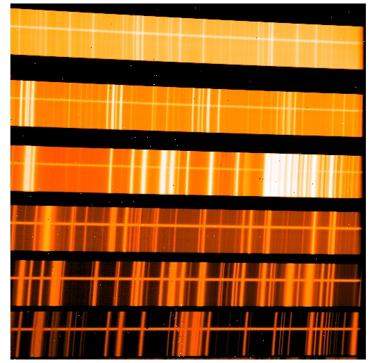
Figure 7: Examples of NIRSPEC two-dimensional spectra in its high-resolution mode for an extended object (left) and point source (right). Wavelength increases from left to right and from bottom to top.
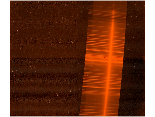
Figure 8: Example of a NIRSPEC two-dimensional spectrum in its low-resolution spectroscopic mode. Wavelength increases from bottom to top.
For reduction of NIRSPEC data, an IDL-based REDSPEC package is available, or try these IRAF tasks designed for low-resolution spectra.
* From the NIRSPEC User's Manual with updates by the KOA team