 |
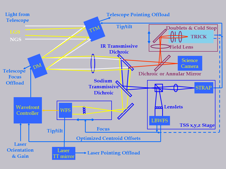
| Fig. 1: Keck LGSAO control loops |
Astronomical observations using natural guide star (NGS) adaptive optics are limited to areas of the sky within ~30 arcseconds of a fairly bright star (R<13.5 using the Keck system). This leaves 99% of the sky beyond the reach of AO. The W. M. Keck Observatory provides a sodium (Na) laser guide star on the Keck I and II telescope to dramatically expand the sky area accessible by AO observations.
In the upper part of the Earth's mesosphere (90±10 km altitude), there is a 5-20 km thick layer rich in Na atoms, deposited by the ablation of micrometeorites. These atoms can be excited and caused to radiate by spontaneous emission by projecting a laser tuned to the Na D atomic transition (589 nm) in the direction of the science target. The magnitude of this artificial guide star corresponds to 9<R<11 on Keck I and 7<R<8 on Keck II, and varies with laser power, beam collimation, and Na column density.
There are four fundamental differences between the operation of the
Keck AO system using the laser guide star (LGS) with respect to that using an
equivalent-magnitude NGS:
|
1. The tip-tilt (TT) of the science object cannot be derived from the LGS since the TT of the LGS includes TT on the upward path to the sodium layer. A separate natural TT reference star near the science
object must therefore be used.
This object can be fainter than that required for full NGS AO correction,
and may also be further from the science target.
A visible TT sensor (STRAP) with 4 avalanche
photodiodes in a quad cell arrangement is used to measure the atmospheric
TT on Keck II. Keck I observers can use STRAP or TRICK, a near-infrared camera with a Teledyne H2RG detector (see Fig. 1). Both sensors allow the use of TT reference stars within 60 arcsec of the science target. STRAP is mounted on a X,Y translation stage to move around the field, while small regions of interest around the TT star are read out from the fixed TRICK field. A choice of H or Ks reflective dichroic beamsplitter is inserted in front of OSIRIS to feed light to TRICK. |
|
|
4. The LGS images are not point-like since they are
being produced in an atmospheric Na layer 5-20 km thick.
The apparent size of the LGS will therefore vary across the telescope
pupil as a function of the distance from the laser launch telescope.
This effect can be mitigated by applying a deformable mirror (DM) loop
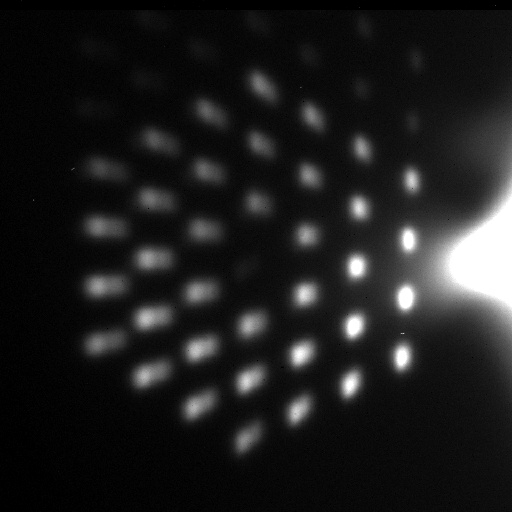
gain which varies across the telescope pupil. Fig. 2 shows the LGS images from the unstacked Keck primary for side launch of the laser; both Keck I and II now launch the laser from behind the Keck telescope secondary mirror which halves the amount of LGS elongation.
|
1. Seeing
The AO correction achievable with LGSAO is somewhat more sensitive to
seeing than that of NGSAO, due to the blurring of the upward-propagating
laser beam under turbulent conditions.
The signal-to-noise ratio (SNR) of the wavefront measurement on the LGS
will be proportional to the reciprocal of its apparent size, which will be
dramatically increased under poor seeing conditions.
The Keck LGSAO system has been successfully operated in visible (0.5 micron)
seeing between 0.3" and 0.9".
Performance estimates given in this document apply to visible seeing of 0.6",
approximately the median for the Keck 2 telescope.
2. Laser beam quality
The full-width-at-half-maximum of the LGS on both telescopes is < 1.5" under excellent seeing conditions.
The spot size depends on laser beam quality and alignment, and the seeing conditions (sqrt(2) times the seeing due to the upward and downward path of the laser).
The wavefront measurement error will be linearly proportional to the LGS
spot size.
3. Returned power
The power returned from the sodium layer is a function of the projected laser
power, the frequency tuning and pulse format of the laser, and the density of
the sodium layer.
The average power output of the Keck I and II lasers are generally 15-20 W and 20 W, respectively. On Keck I the LGS equivalent R magnitude is 9 to 11 and on Keck II it is 7 to 9 magnitude.
The return has been observed to vary by over a factor of 4 from run
to run.
The SNR of the wavefront measurement is proportional to the counts per
subaperture.
4. TT reference magnitude
The magnitude of the TT reference determines the quality of the tip-tilt
control, but not the control of higher order modes.
Thus the image degradation suffered with a faint TT reference is a broadening
of the PSF core, rather than a reduction in the ratio of the power in the core
to that in the halo, as is the case with a faint NGS.
The TT bandwidth and measurement noise both increase for fainter stars,
and begin to dominate the error budget for TT
references with R>15.
The LGSAO system has been operated for science with TT reference stars as faint as
R=19.
Note that the PSF when using faint TT reference stars has a unique structure,
since high-order aberations are still well corrected.
This results in a PSF with little power in the seeing-limited halo, but no
clear diffraction-limited core.
The TRICK requirement is to use stars as faint as 16th magnitude in H or K-band.
5. TT reference separation
We have measured the isokinetic angle, the angle at which the phase becomes
decorrelated by 1 radian rms due only to TT, to be 72" at 2.1 microns on
one occasion (07/27/04).
This may not be typical.
Above a separation of ~40", tilt anisoplanatism becomes a dominant term in the
LGSAO error budget.
Under most circumstances, the science object will be kept near the telescope
optical axis (or science detector center). The
TSS stage translates the STRAP TT sensor
and LBWFS across the focal plane to reach the TT reference; for TRICK use the region of interest is moved to acquite the TT reference.
Certain regions of the TSS focal plane and TRICK detector are currently inaccessible due to
vignetting or bad pixels, respectively (see
TSS view), thus the PA of the science instrument
may be constrained for TT references >10" from the science target.
6. Elevation
As with seeing, the corrected image quality is more strongly dependent on
elevation in LGSAO than in NGSAO.
Under median seeing conditions on 02/04/04, LGSAO corrected images with
a V=15 TT reference at 49° elevation had a Strehl of only 0.06, while
that near zenith with a similar TT reference was 0.15.
We are prohibited from projecting the laser below 20° elevation.
7. Pointing accuracy
Since TT control is performed by STRAP or TRICK placement of the science object on the science instrument is determined by the positioning accuracy of these devices rather than by the less accurate field steering mirrors (FSMs) as is the case for NGSAO. The
TSS stage which positions STRAP and the LBWFS has proven to be repeatable to ~4 microns rms, corresponding
to 3 mas on sky.
For more information please contact Jim Lyke or R. Campbell: (randyc or jlyke @keck.hawaii.edu).