Summary
This document describes the operation of the IDL-based IFU Centerup
tool for centering a target in the ESI IFU. Given a dome or sky flat
acquired with the IFU, and an IFU spectrum of the target, this
procedure will determine and print the telescope move required to
bring the target to the center of the IFU. The observer then needs to
execute the given move command to complete the centering.
Requirements
- Dome flat acquired with the ESI IFU.
- IFU spectrum of target.
Invocation
Procedure
Follow these steps to center your target on the IFU.
- Configure ESI. Set ESI up for echellette-mode
spectroscopy, being sure to set the CCD integration time to an
appropriate length to produce a good spectrum.
- Acquire target at IFU. Have the OA acquire the target,
send it to the IFU pointing origin, and begin guiding.
- Take spectrum. On the centerup tool, clock the
Acquire button to Acquire a spectrum of sufficient depth to
see continuum (or prominent spectral lines).
- Identify region of interest.
Note the location of a spectral region which has:
- strong continuum or emission, and
- spectrum running as close to the column direction as possible.
Note the first and last rows and columns in this region.
- Select images. On the centerup tool, enter the name of the
Target Image (which you just acquired) and the Flatfield
image (which you took in the afternoon). You can use the
Browse... buttons to select images from the data directory,
or click the Last button to select the most recent
spectrum.
- Define analysis region. Enter the coordinates for the
region of interest in the corresponding boxes labeled
X start, X end,
Y start, and Y end.
- Analyze images. Click the Analyze button. The
tool will then:
- Read in the ESI images.
- Extract the region of interest and sum the rows.
- Remove cosmic rays in the region of interest.
- Analyze the flatfield image to determine the slitlet endpoints.
- Measure relative flux among slitlets to determine decentering in
the direction across the slits (U axis).
- Measure sum of the flux profiles within all slits to measure
decentering in the direction along the slits (V axis).
- Derive and display the telescope move required to center the
target.
- Move telescope. Click the Move button to
offset the telescope.
- Iterate as required. Repeat preceding steps until
convergence is achieved (i.e., recommended moves are less than 0.2
arcsec or so).
Notes
- The region of interest should be chosen to include a decent
amount of signal, either continuum light from the source or a strong
emission feature.
- Since no correction is made for curvature of the orders, the
region of interest should be chosen so that the spectral direction is
well aligned with CCD columns; otherwise, the signal will be
“smeared”.
Screenshots
Main Window
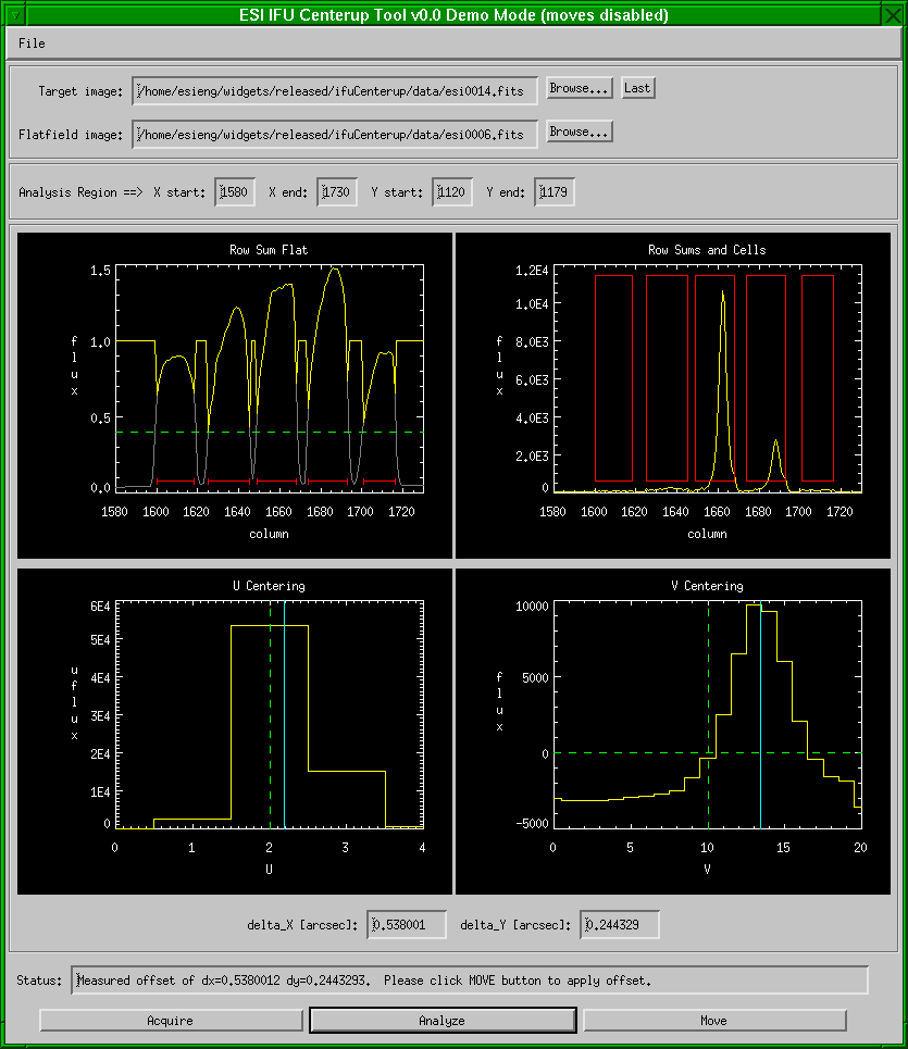
ATV window
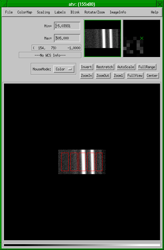
The ATV window displays the target spectrum and overlays the slitlet
regions within the region of interest as red rectangles.
Row Sum Flat Plot
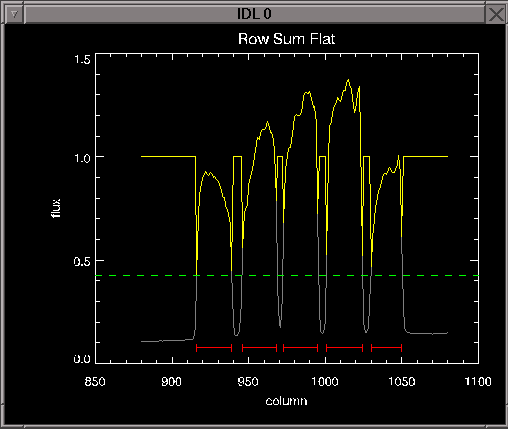
This plot shows a row sum of the region of interest in the flatfield
spectrum and is used to determine the slitlet endpoints. Elements:
- green line: threshold value for determining slitlet endpoints
- yellow line: row sum of flatfield after thresholding; regions below threshold set to 1
- grey line: row sum of flatfield prior to thresholding
- red lines: slitlet extents
Row Sums Plot
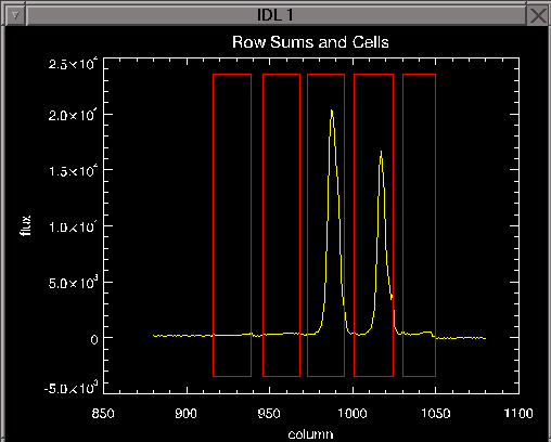
This plot shows the row sum of the region of interest target spectrum and is used to measure the decentering of the target. Elements:
- yellow line: row sum of target spectrum
- red lines: slitlet extents
If the profiles within each slitlet are decentered from their
respective boxes, that indicates decentering in the direction along
the slitlets (V axis). The relative distribution of light among the
slitlets indicates the centering in the direction perpendicular to the
slits (U axis).
U Center Plot
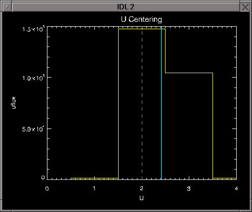 This plot shows the decentering in the axis perpendicular to the slit
direction. Elements of note:
- yellow line: relative amounts of light in slitlets
- blue vertical line: measured center
- green vertical line: desired center
V Center Plot
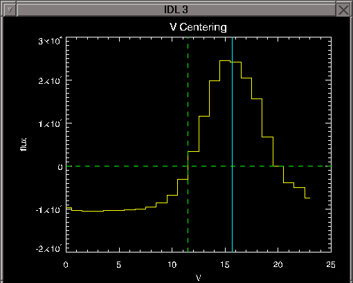 This plot shows the decentering in the axis parallel to the slit
direction. The mean value of the profile is subtracted so that only
the values above the mean are included in centroiding. Elements of
note:
- yellow line: sumed profile across all slitlets
- blue vertical line: measured center
- green vertical line: desired center
- green horizontal line: mean profile level


