Background
The Lantronix terminal server is a device which coordinates
communication among the various controllers in DEIMOS. DEIMOS
has two Lantronix terminal servers:
The first indication of a problem with the Lantronix terminal
server on DEIMOS might be problems commanding motors. Other
symptoms may exist as well but this problem can be confirmed by
running testAll on polo. If the Lantronix
unit is unresponsive, the return from this command will indicate
a problem communicating to the Lantronix. The first thing to
try is the soft reset
procedure, which can be done remotely. If this should fail,
the following more serious procedure may be used to power cycle
the Lantronix unit.
Procedure for Cradle Lantronix
Follow these steps to cycle power to the Lantronix terminal server
in the DEIMOS cradle:
- Remove Bay D cover. To access the Lantronix power
switch, remove the Bay D cover by undoing the red thumbscrews
and lifting the cover off.
- Locate Lantronix. The terminal server should be
located between the blue AC outlets and the Netgear hub as
shown in this photo.
- Cycle power. Use the rocker switch on the front (top)
of the Lantronix unit to turn power off. Wait a few seconds,
then turn power back on. Figure 3 shows
the Lantronix terminal server and the rocker power switch.
- Verify communications. Execute the
DEIMOS testAll script to confirm that the DEIMOS host
computers are able to communicate with the Lantronix unit. If
so, then proceed with re-installing the rear cover. If not,
check cabling as described next.
- Check cabling. Inspect the cabling at the back of
the Lantronix, including the coax cable and adapter. Confirm
that all cables are securely plugged in. If none are suspect,
you might try unplugging individual cables and plugging them
back in. In particular, confirm that the AUI (10Base-2) adapter
is firmly plugged into the port on back of the Lantronix.
- Re-verify communications. Execute the
DEIMOS testAll script again to confirm that the
DEIMOS host computers are able to communicate with the Lantronix
unit. If so, then re-install the cover. If not, try another
power cycle. If this fails to fix the problem, then the
Instrument Technician should configure and install a spare
Lantronix. Night staff should not attempt this repair.
Procedure for Barrel Lantronix
Follow these steps to cycle power to the Lantronix terminal
server in the DEIMOS barrel:
- Rotate DEIMOS. Rotate DEIMOS to access
electronics bay 3. The electronics bays are located around
the large ring-like structure at the back of the instrument.
They are labeled with numbers and contents. There are three
ways to set the instrument rotator position:
- Have the observer rotate DEIMOS to an angle of 0°
or 180° from the DEIMOS
rotator GUI.
- Have the OA rotate DEIMOS to physical drive
angle 90° or -90°.
- Alteratively, you can rotate by putting the DEIMOS
hand paddle in manual mode, turning the mode selector to 0
(fast jog), then using the FWD or REV buttons to turn the
instrument until you can access bay 3.
These put the bay on the left and right hand sides of the
instrument, respectively, when viewed from the rear of the
instrument looking toward the telescope.
- Appy band brake. Use the lever at the left front of
DEIMOS to prevent rotation of the barrel and protect the drive
motor from damager. See figure 1.
- Remove Bay 3 rear cover. To access the Lantronix
power switch, remove the cover shown in figure
2. Please note the following:
- You only need a flat-blade screwdriver. A suitable
flat-blade is available right by the DEIMOS hand paddle.
- All fasteners are 1/4 turn captured.
- Do not undo the allen bolts visible on the panel.
- This panel "wraps around the instrument". In other
words it will be sort of L-shaped when removed.
- Cycle power. Use the rocker switch on the front
of the Lantronix unit to turn power off. Wait a few seconds,
then turn power back on. Figure 3 shows
the Lantronix terminal server and the rocker power switch.
- Verify communications. Execute the
DEIMOS testAll script to confirm that the DEIMOS host
computers are able to communicate with the Lantronix unit. If
so, then proceed with re-installing the rear cover. If not,
check cabling as described next.
- Remove side cover. To access the cabling at the back
of the barrel Lantronix, remove the side cover using a
5/16” T-handle hex key. Figure 4
shows the cover.
- Check cabling. Inspect the cabling at the back of
the Lantronix, including the coax cable and adapter. Confirm
that all cables are securely plugged in. If none are suspect,
you might try unplugging individual cables and plugging them
back in. Figure 5 shows the cabling as
seen when the side access panel has been removed.
- Re-verify communications. Execute the
DEIMOS testAll script again to confirm that the
DEIMOS host computers are able to communicate with the Lantronix
unit. If so, then proceed with re-installing the rear cover.
If not, try another power cycle. If this fails to fix the
problem, then the Instrument Technician should configure and
install a spare Lantronix. Night staff should not attempt this
repair.
- Re-install covers. Getting the covers back on can
be a little tricky. Seat all the 1/4 turn fasterners in their
sockets first then go around turning them.
- Release band brake. Don't forget when leaving:
release the band brake, set hand paddle in computer mode.
Figure 1. DEIMOS band brake
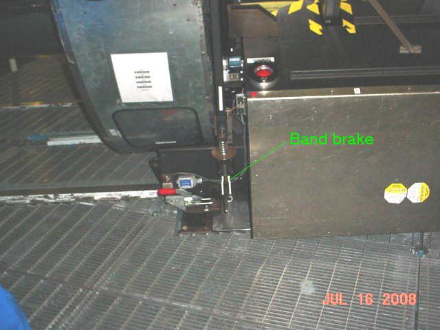
Band brake. Push lever down to engage. Pull up to release.
Figure 2. DEIMOS electronics bay 3
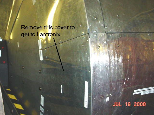
Panel to be removed. Only undo the flat blade 1/4 turn
quick release fasteners. Do not try to undo the hex key screws
that are visible in the panel.
Figure 3. DEIMOS Lantronix terminal server
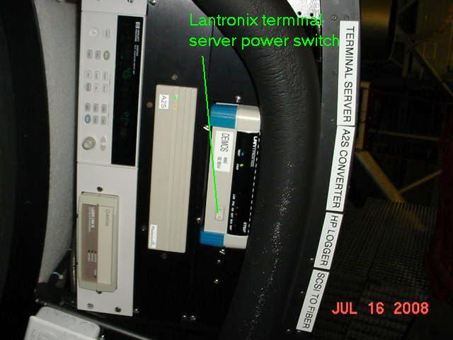
Lantronix terminal server in electronics bay 3.
Figure 4. DEIMOS electronics bay 3, side view
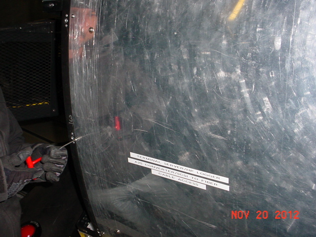
Side view of the panel which must be removed to access
cabling on the DEIMOS barrel Lantronix unit. This requires a
5/16” T-handle hex key.
Figure 5. DEIMOS Lantronix cabling
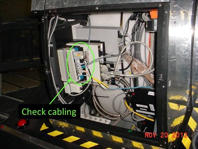
View of DEIMOS Lantronix with side panel of bay 3 removed,
showing cabling.